Continue to Site

Welcome to our site!

Electro Tech is an online community (with over 170,000 members) who enjoy talking about and building electronic circuits, projects and gadgets. To participate you need to register. Registration is free. Click here to register now.

  • Welcome to our site! Electro Tech is an online community (with over 170,000 members) who enjoy talking about and building electronic circuits, projects and gadgets. To participate you need to register. Registration is free. Click here to register now.

Problems with IR2110

Status
Not open for further replies.

chicheme

New Member
Hi all, I'm new to this forums

I've being trying to build an H-bridge driver using 2 IR2110, but I can't get it to work for now.

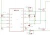
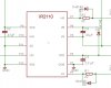
I've attached the schematics that I'm using now.

I would like to know if someone sees any mistake. I'm using TTL of 3,5Vpp and 1 KHz at HIN and LIN and I'm getting a DC voltaje at LO arround 14 volts and 0 volts at HO.

I hope you can help me

Thanks for your time
 

Attachments

  • Unbenannt.JPG
    Unbenannt.JPG
    49.9 KB · Views: 3,462
Last edited:
I need to see the entire schematic with the output MOSFETs connected,and power supply connections. I suspect that the IR2110 uses the pulse output of the whole circuit to "pump up" the voltage required to supply the high drive.

Bob
 
Last edited:
Heres is the schematic with the MOSFETS

I'm using a resistor of 100 ohms as a test load to see how it behaves, but for now I can't get the IR2110 to work. Any sugestions about the voltage that I should use for the capacitors? I do not understand the calculations for the bootstrap capacitor in the aplication note... :confused:

Thanks for the help
 

Attachments

  • Unbenannt.JPG
    Unbenannt.JPG
    64.2 KB · Views: 11,723
Do you have a voltage on Vb with respect to Vs? this is the internal charge pump that high side drives the top FET. If this voltage is not there, you will not get the top FET to switch.

have you also tried it with no load (or 100k), as the bootstrap cap is only designed to pulse a short amount of current into the gate of the FETs and not drive a heavy load...
 
C3 should be between 1 and 10uf. I often use IR2110 IC's and never use less than a 2.2 uF capacitor on C3.

Also whats the purpose of D3 and D4? I have never seen that recommended in any driver IC data sheets.
 
I was usign 0,47µF on C3 because that's the one that they use in the application note (see attached file) in figure 28A. An since I'm trying to buld something similar to figure 27 I thought I would be needed. I also saw someone recomending to use that diode somewhere else here I think.

I'll try doing the changes you guys are sugesting and let them you know if it works, hopefully it will.

Thanks!!
 

Attachments

  • an-978.pdf
    425.2 KB · Views: 1,551
Also whats the purpose of D3 and D4? I have never seen that recommended in any driver IC data sheets.

The diodes will turn the fets off quicker by bypassing the 22ohm resistor. Maybe to reduce switching losses?
 
diodes in the mosfet drive lines used with IR2110

HI to all.
The diodes are used to slightly increase the 'dead time' which helps ensure that both mosfets are never on at the same time.
Hope this helps - Jeff M
 
Status
Not open for further replies.

Latest threads

New Articles From Microcontroller Tips

Back
Top