Continue to Site

Welcome to our site!

Electro Tech is an online community (with over 170,000 members) who enjoy talking about and building electronic circuits, projects and gadgets. To participate you need to register. Registration is free. Click here to register now.

  • Welcome to our site! Electro Tech is an online community (with over 170,000 members) who enjoy talking about and building electronic circuits, projects and gadgets. To participate you need to register. Registration is free. Click here to register now.

problems being faced in making a 0-12V variable dc supply.

Status
Not open for further replies.

arin23

New Member
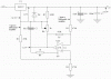
hello,there.I want to make a 0 to 12V variable dc power supply using lm 723.since Vref has to be more than 2V(for diff amps in 723 to work)my o/p is in the range 2 to over 14V. The problem i am having is in finding a virtual ground of around 2V.I put a 741op amp and used it as a unity follower with Vref of around 2V as i/p and +Vcc connected to unreguated supply and -Vcc to ground.Can i use op amp wid -Vcc as grnd this?
With this cofiguration the maximum Short ckt current is arnd 32mA whereas i need it to be arnd 100mA.Also when i short 723 ic's o/p to o/p of 741 the op amp is not working as unity follower.Its o/p and thus -ve i/p goes to the value of o/p of 723 and not of Vref.
how can i increase the current value..even pass transistor isnt helping
Please help .I need to make the circuit urgently.thanks in advance
 

Attachments

  • simulation's bmp.doc
    26.5 KB · Views: 301
A 723 is a very old device and a poor choice with which to try to build a 0 to 12V supply. Why not use a modern regulator, which will allow you to go to 0V without added circuitry?
 
You need a negative power supply.

You can easily create a negative rail by adding a voltage doubler.

Here's an example:
**broken link removed**

You can also use an LM317 plus a :mu:A741 or similar general purpose op-amp which will use far fewer components.

**broken link removed**

0 to 13.8V LM317 Power Supply
 
The LM317 has the advantage of being a cheap common IC.

The LT3080 has the advantage of simplicity.

I can remember having this conversation with you before. :D
 
The LM317 has the advantage of being a cheap common IC.

The LT3080 has the advantage of simplicity.

I can remember having this conversation with you before. :D
And as I probably previously stated, to me spending a few extra bucks for an LT3080 (they cost about $4) is likely balanced by the extra cost of the 16 or so added parts needed to use the LM317 for this application (unless you happen to have them already in your junk box). Also the construction of a supply with 4 parts is certainly a lot easier and faster then one with 20 parts.

Of course I'm a great fan of simplicity, but it's certainly a personal choice as to which is preferable.
 
Another disadvantage with proprietary parts is that if they go obsolete you're pretty stuck.

If this is just for a couple I and I didn't mind waiting for the parts then I'd probably get samples if I can, order form a distributor or risk buying on ebay.

If I wanted to put this into long term production I would seriously consider using the more complex circuit with common parts that will never go obsolete.
 
The LT3080 is a significant improvement over the 317 so I would expect it to be around awhile, and likely cloned by other manufacturers in the future. But you point is well taken, it's not good practice to build a production device with single-source parts, although it's probably frequently done.

You can also buy the LT3080 directly from the Linear Tech website.
 
thanx to all for the help.
to Hero999: i chose an op amp jst bcoz a zener wont provide good regulation.And when i performd d simulation it didnt work pretty well.
Can u suggest me a better ckt using 723 ic only(my teacher has told me to use only this ic)??and a proper 2V pt in the ckt which i can use as d -ve terminal of the o/p supply??
thanx is advance
 
Look at this **broken link removed**.
 
thanx to all for the help.
to Hero999: i chose an op amp jst bcoz a zener wont provide good regulation.And when i performd d simulation it didnt work pretty well.
Are you talking about my circuit or yours?

In my circuit the zener only roughly regulates the negative input to the µA741. It's not responsible for regulation of the output.

The idea is that you build the zener supply which provides a negative rail for the op-amp. If you power it from a single 20V supply then it won' work.

Can u suggest me a better ckt using 723 ic only(my teacher has told me to use only this ic)??and a proper 2V pt in the ckt which i can use as d -ve terminal of the o/p supply??
thanx is advance
My circuit works by subtracting the voltage reference from the output by taking the normal normal 0V node below 0V by the same voltage as the reference. U2 is just a differential amplifier which performs the subtraction.

Have a look at the website for more information.
https://www.silicontronics.com/index.php?action=ezportal;sa=page;p=19

My attachment shows the typical voltages at different parts of the circuit when the output is set to 13.8V.

I'm sure you can use a similar principle for the LM723.
 

Attachments

  • 0 to 13.8V voltages.gif
    0 to 13.8V voltages.gif
    14.2 KB · Views: 587
Last edited:
Status
Not open for further replies.

Latest threads

New Articles From Microcontroller Tips

Back
Top