Continue to Site

Welcome to our site!

Electro Tech is an online community (with over 170,000 members) who enjoy talking about and building electronic circuits, projects and gadgets. To participate you need to register. Registration is free. Click here to register now.

  • Welcome to our site! Electro Tech is an online community (with over 170,000 members) who enjoy talking about and building electronic circuits, projects and gadgets. To participate you need to register. Registration is free. Click here to register now.

problem with the ADC, the microcontroller PIC16F877A

Status
Not open for further replies.

francisco6329

New Member
Hi, I speak Spanish, so I translated it in google

I have a problem with the ADC, the microcontroller PIC16F877A, I'm using 6 analog inputs, AN0, AN1, AN2, AN4, AN5 and AN6, and use AN3 VREF + which is connected to 5Vdc.

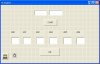
4 analog input has a 10K potentiometer, which sends a 0 - 5Vdc. PIC's ADC converts the digital signal input selected and then sends that value for serial port in visual basic 6 program is the formula to convert to the corresponding analog value.

My problem is that there are two entries that have nothing plugged in, and should read 0 volts, but the PC when it displays the information in these channels put random values. also happens when I send 0 volts potentiometers.

also the maximum value that can appear is 5V, and sometimes appears 7.

Another problem is off the microcontroller and the PC sends a data through the serial port, the power LED flashes.
 
That chip has dependent ADC which means if you set AN0 to AN6 as ADC more then likely you have set more pins on.

The PCFG3:pCFG0: A/D Port Configuration Control bits have to be set right.

Page 130 data sheet. https://www.electro-tech-online.com/custompdfs/2011/11/39582b.pdf

And if there floating you will get random values

Post your code it will help a lot to see what is going on

Que chip tiene ADC depende lo que significa que si se establece AN0 a AN6 como ADC más que probable que haya puesto más pines.

El PCFG3: PCFG0: A / D Puerto bits de control de configuración tiene que ser corregido.

Página 130 hoja de datos https://www.electro-tech-online.com/custompdfs/2011/11/39582b.pdf

Y si hay flotante se obtendrán valores aleatorios

Publicar su código que va a ayudar mucho para ver lo que está pasando
 
Last edited:
The question is very vague... From your description the PC program is at fault, however we do not know what your passing to the PC from the micro.. this may be a signed / unsigned problem.. I need to see both parts of the code..
 
thanks for answering.

Here is the code of the PIC, the program has three parts, 4 steps to follow:
1. Pulse hopes to start the PC
2. checks that will make selected channel and converts the selected channel digital
3. serially transferred two bytes of the result of the ADC.
4. adds one to the variable CHANNEL to select another channel, and skip to step 2.

and the visual basic project, there is the Start button that sends the micro to start sending data, when pressed sends the byte H22 is valid data byte, and then the data value H48 is the first channel AN0, so the PIC starts to send data.
 

Attachments

  • ADC RS-232.asm
    9.4 KB · Views: 147
  • code visual basic 6.txt
    2.4 KB · Views: 212
  • form visual basic.JPG
    form visual basic.JPG
    80.7 KB · Views: 198
There is a very strong chance that your sequence can get out of sync.... It would be easier to send the whole string in one or at least send 'A' the L.B ,H.B....'B' L.B, H.B etc... then if a framing or overrun occurs you don't fall out of sync..
 
then I have to make a communication protocol, as you say:
"A" LB HB "B"

"A": beginning of the message
LB: lower data
HB: upper data
"B" end of message

I will try, if not used Start sequence, he received the data backwards and showed a value High.
 
Thanks guys, I found what was the problem, the problem was a bad connection, I was not putting the analog signals in the respective channels, and then when the channels are connected have nothing random reads between 0 and 3.4 volts.

Since the project is fine, but now I have a problem, when under the value of the potentiometer to produce 0 volts, minimum resistance to the corresponding channel starts to generate random values. If the ohmic value rises begins to function well. I think putting an op-amp voltage follower mode between the potentiometer and the analog input impedance of the circuit better.
 
Status
Not open for further replies.

Latest threads

Back
Top