Continue to Site

Welcome to our site!

Electro Tech is an online community (with over 170,000 members) who enjoy talking about and building electronic circuits, projects and gadgets. To participate you need to register. Registration is free. Click here to register now.

  • Welcome to our site! Electro Tech is an online community (with over 170,000 members) who enjoy talking about and building electronic circuits, projects and gadgets. To participate you need to register. Registration is free. Click here to register now.

Problem with Predko's El Cheapo

Status
Not open for further replies.

bonxer

New Member
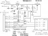
I just made an El Cheapo programmer with the board supplied with Myke Predko's PIC book. I've tested for continuity and accidental bridges, and everything seems to check out. When I plug in a 16.8v 300mA supply, the output of the 7812 regulator comes out anywhere between 10.5 to 11.3 volts. :shock: This seems to be the opposite effect that should be occurring, the two diodes should be causing the voltage to rise UP to 13 or above. All of the components (resistors, caps, regulator) become extremely hot to the touch within seconds of plugging it in. I have not yet connected it to a computer as something seems really wrong.

Anyone ever experienced this? Any suggestions before I go through and desolder all the components to test them individually :?:
 
sounds like you may have something drawing too much current out of that regulator... that would cause a voltage droop on it as well as causing all that heating... disconnect the output of the regulator and try powering it up. does the regulator still heat up? measure the output voltage of it while disconnected, is it outputting the desired 13v?

if not, then put a multimeter in current measure mode and connect it between the output of the regulator, and the rest of the circuit. that will tell you how much current it's drawing... for something like a PIC programmer it shouldn't be drawing much current at all so if it is, then you need to check the rest of your circuit to find out why so much is being drawn.
 
I have unsoldered the regulator and stuck it in a breadboard and connected it with diodes, and it outputs the desired 13.2 volts. I shall try the multimeter current measure soon.

willb: The circuit diagram from Myke's page follows. This is a more recent version. Transistor Q2 is a 3906 bipolar transistor in the version in the book.
 

Attachments

  • parprog.jpg
    parprog.jpg
    88.4 KB · Views: 820
With such a simple circuit there are very few possibilities for drawing excessive current, pretty well only C4, Q1 and Q2. Assuming you have put all the components in the correct places?.

A more likely reason is a short across tracks on the PCB.
 
I rebuilt the circuit with fresh components on a breadboard, and everything works out. All voltages are fine, and current is fine. It's still getting hot, but it's stable. Then I take all the components off the PCB, start replacing them one at a time, and it drops as soon as I put the zener diode in. I guess there is a bad trace somewhere too.
 
bonxer said:
I rebuilt the circuit with fresh components on a breadboard, and everything works out. All voltages are fine, and current is fine. It's still getting hot, but it's stable. Then I take all the components off the PCB, start replacing them one at a time, and it drops as soon as I put the zener diode in. I guess there is a bad trace somewhere too.

It sounds like there's a short across R1, although if it's a PCB trace problem it may be no where near R1.
 
Hello.
I have the same book and PCB. This might seem a little strange
to ask, but are using the "78L12"? This regulator is used to limit
current. The book recommends that you use only this regulator.
Also, after looking at the diagram and then looking
at the PCB, it seemed that one of the transistors might be drawn
backwards on the PCB. My PCB is only 50% completed, If figure
this out, please let us know what you find .

Good Luck
Gordon
 
Yes I am using the 78L12. It's used to regulate the supply voltage, not current. It allows you to use various sized higher voltage power transformers and guarantees that you get a 12 volt output. The two diodes adjust it to add a little more to get it up to high level programming voltage. Lower regulators wouldn't source enough voltage for programming, and higher regulators would be too much, so yes, use only this one.

As for the backwards transistor, after looking at it, I think you may be right! Transistor Q1, the 2N7000, should have its source connected to ground. But instead, if you insert it according to the silkscreen placement, the drain is grounded. :shock:
 
Hi Bonxer
If you have the second edtion of this book, goto page 606.
In section "1" is paragragh that sounds alot like the trouble
your having. Basically it states if the power supply doesn't
output between 14.5V and 16V the regulator will get hot and
it will not be stable.

Hope this helps.
Gordon
 
Status
Not open for further replies.

Latest threads

New Articles From Microcontroller Tips

Back
Top