Continue to Site

Welcome to our site!

Electro Tech is an online community (with over 170,000 members) who enjoy talking about and building electronic circuits, projects and gadgets. To participate you need to register. Registration is free. Click here to register now.

  • Welcome to our site! Electro Tech is an online community (with over 170,000 members) who enjoy talking about and building electronic circuits, projects and gadgets. To participate you need to register. Registration is free. Click here to register now.

Problem with laptop monitor and controller board

Status
Not open for further replies.

HyOxy-8

New Member
Hi!

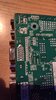
I just received the controller board for my laptop monitor witch I intended to use as a secondary screen. It was working just fine before I took it apart from the HP laptop. The LCD model nº is B154EW08 V1
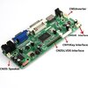

The board has the correct model number but I just noticed it says 17" 1440 x 900, and my screen is 15" 1920 x 1080. Don´t know if that´s important or not.

After I power it up with a proper 12V 4A capable adapter, I can only see 1/7 of the screen with really bad quality, the rest has those weird lines. It seems broken at first glance but I doubt it.

I tried changing the Hertz and resolution settings, different HDMI and VGA cables as well as a different PC but it stays more or less the same.

Any help is appreciated!
Thanks

118671525_357827388720038_2027958612049384349_n.jpg118765110_939624273224276_5386520289720861250_n.jpg118785704_983755358764169_7934602737575018563_n.jpg118831437_628886190978357_4102200014099311438_n.jpg118833020_724832941407092_7360680195048669333_n.jpg118878694_1740275876127984_2811132842990667850_n.jpg
 
looks to me like the controller isn't compatible with the screen..... the LVDS cable has fewer pins than the controller LVDS header
 
looks to me like the controller isn't compatible with the screen..... the LVDS cable has fewer pins than the controller LVDS header

Probably yeah.... I´m speaking with the seller right now. He says that he will send me the updated program... and that I need a burner to install it in the board... but do I really need it? I use win10 can´t I just update drives normally?
 
Presumably he is talking about firmware for the board, so you may need a suitable "burner" to upload it.
Interesting gadget.
 
Presumably he is talking about firmware for the board, so you may need a suitable "burner" to upload it.
Interesting gadget.

Ok, I´m asking him again about the burner program, the first time he ignored me.... where can I get it?

Btw, before he sent me the updated drive, he asked me if I had a USD flash drive to update the board..... Why the hell do I need it since the board doesn´t have a usb port in the first place?
 
The thing that's really bugging me here is, why have you not arranged to return the board and get a more suitable version or refund? Also, it's possible that it is actually faulty. Just because it's new doesn't guarantee it works.

But anyway, I'm wondering if this guy knows what he is talking about.

I notice there is at least one jumper on the board. Is it possible this lets you set the screen size?

The internet might be your best friend here. Find the part number or model number of the board and type it into your favorite search engine. Same goes for the processor on the board. If it's a dedicated chip then it's likely the manufacturer has published a demo circuit and the board is based on this.

So, the board has no data interface that your computer would normally use, which is why you can't update it in a normal way from windows.

As to USB, you can't eliminate it entirely because the port might be there but just not have a connector (or at least, not a USB connector). But even if it has, you still have the problem of how to actually use it. I can't imagine the processor is sophisticated enough to update itself directly from a drive. If USB is present it would probably connect to a PC.

Most likely there is a simple programming interface on the board. It might simply be a serial data connection or it might require some extra piece of hardware - the previously mentioned "burner".
 
The thing that's really bugging me here is, why have you not arranged to return the board and get a more suitable version or refund? Also, it's possible that it is actually faulty. Just because it's new doesn't guarantee it works.

Well after 3 days of going back and forth with the seller, he offered to send me an updated board.... I didn´t ask for a refund because the guy was replying fast and seemed to be helping me by sending the updated driver and so on. His knowledge about how to burn it is 0, so a waste of time really.

I notice there is at least one jumper on the board. Is it possible this lets you set the screen size?

So, the board has no data interface that your computer would normally use, which is why you can't update it in a normal way from windows.

As to USB, you can't eliminate it entirely because the port might be there but just not have a connector (or at least, not a USB connector). But even if it has, you still have the problem of how to actually use it. I can't imagine the processor is sophisticated enough to update itself directly from a drive. If USB is present it would probably connect to a PC.

Most likely there is a simple programming interface on the board. It might simply be a serial data connection or it might require some extra piece of hardware - the previously mentioned "burner".

There are 2 unused connectors, a 3 pin labeled as "IR interface" and another for a speaker (the inverter is what powers the back light).
I can´t find anything that has 4 pins for a usb connection, but like you said I still need the burner.

I´ll try to search it like you suggested and see what I can find. Hope it´s not to complicated, pc stuff is not my strength. I´ll report soon.
 

Attachments

  • s-l500.jpg
    s-l500.jpg
    28 KB · Views: 232
JTAG connections are likely somewhere along that row of pads behind the VGA connector. if the pins are labeled look for TDI, TDO, TCK, TMS, and possibly TRST (the reset is an optional pin on JTAG interfaces)... actually look for those abbreviations elsewhere on the board, because they usally use a bed-of-nails fixture at the factory, and so those signals don't HAVE TO go to a header... but there might be bare copper pads on the bottom of the board for the test fixture pogo pins to connect to.
 
I now know 100% more about JTAG than I did a minute ago. Thanks!
 
JTAG connections are likely somewhere along that row of pads behind the VGA connector. if the pins are labeled look for TDI, TDO, TCK, TMS, and possibly TRST (the reset is an optional pin on JTAG interfaces)... actually look for those abbreviations elsewhere on the board, because they usally use a bed-of-nails fixture at the factory, and so those signals don't HAVE TO go to a header... but there might be bare copper pads on the bottom of the board for the test fixture pogo pins to connect to.

I looked everywhere for those abbreviations but I cant find them. There are 4 suspicious pins behind the VGA that are labled 5V, RDX, TXD and GND
 

Attachments

  • 119882216_360792141757409_5634826096895410498_n.jpg
    119882216_360792141757409_5634826096895410498_n.jpg
    62.9 KB · Views: 244
Looks like a TTL serial port. Something to connect some kind of interface to. It's probably connected to some pins on the main chip. If you can find a data-sheet for that it might say what kind of data it wants.
 
Status
Not open for further replies.

Latest threads

New Articles From Microcontroller Tips

Back
Top