weegee
New Member
Hi there, im new to these forums, but Hi to everyone: anyway on to the problem:
I have designed a circuit that will be run from a pic processor:
**broken link removed**
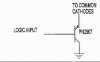
The circuit that you will se is the multiplexing part, my problem is with the sinking of the Common Cathode on the display's, eg when a display is lit, the current is sinked through the 4-16 line decoder, how can I rewire this so that the output from the decoder switches the cathode to ground, rather than sinking the current directly?
any help would be greatly apprecited
Also is a PIC16F84A Running @ 4 MHz likely to be fast enough to update the display, using 7 lines as a parallel output, and 1 output as a strobe, whice counts on the binary counter, which updates the 4-6 decoder.
BTW: the 7 wires at the bottom of the diagram are the 7 parallel data outputs.
Thanks
WeeGee
I have designed a circuit that will be run from a pic processor:
**broken link removed**
The circuit that you will se is the multiplexing part, my problem is with the sinking of the Common Cathode on the display's, eg when a display is lit, the current is sinked through the 4-16 line decoder, how can I rewire this so that the output from the decoder switches the cathode to ground, rather than sinking the current directly?
any help would be greatly apprecited
Also is a PIC16F84A Running @ 4 MHz likely to be fast enough to update the display, using 7 lines as a parallel output, and 1 output as a strobe, whice counts on the binary counter, which updates the 4-6 decoder.
BTW: the 7 wires at the bottom of the diagram are the 7 parallel data outputs.
Thanks
WeeGee