coolkid
New Member
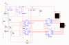
Still very new to this,I hope you guys will help me in this journey.I am tasked to create a 24hr clock using 74ls93 ic and im using 74ls47 bcd decoder and 7seg anode led.
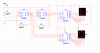
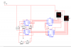
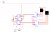
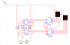
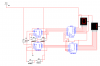
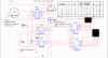
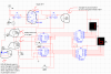
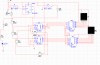
Image below shows what i have done so far,and i not sure why the numbers are liddat.Please help
Image below shows what i have done so far,and i not sure why the numbers are liddat.Please help