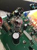
In the face of not having much in the way of fault finding skills or test equipment, and with the given that you replaced some components after which it worked for a while, then stopped again, I think it's not a bad idea to re-work all the soldered joints on the board. You only need to melt each one with your iron and add a tiny bit of fresh solder (keep the solder sucker handy, as these things occasionally go sideways). Blanket coverage like this is crude but usually effective if the problem is simply a bad joint - trying to track one down individually can be like trying to catch pixies. Or elves.
Running it for hours at a time won't burn the op-amps out, or any other part. It is designed to run indefinitely. Thermal faults can occur - ie ones that only show when it's warmed up past a certain point. Hard to trace. However if it's not working from power-up, this is quite unlikely.
You haven't said in what way it doesn't work. Is it no power at all, or no sound on both channels, or on just one channel, or buzzing, or very quiet, affected by the controls, do the VU meters show any activity, or what? Is the new fault the same as the original fault? Symptoms like these can give a big clue as to where the fault lies.
There are some voltages given on the schematic. Check all of these. I'd take a punt on any more than 10% different to the drawing as needing further investigation.
A quick and dirty check for op-amp functionality is, does the voltage on the inverting input, match (or is very close to) the output? If it's different by more than 100mV (let's say) it probably indicates a fault associated with that op-amp - use the schematic to figure out candidates for testing. It being different by design is possible, but unlikey (eg, if it's used as a comparator, or to only kick in under certain conditions)
Check transistor voltages - for linear circuits the base should be around 0.6v higher (for NPN) or lower (for PNP) than the emitter. If it's around 0.7v then something is likely causing the transistor to saturate. If it's much more than that you could have a faulty transistor. Much less than 0.6 and the transistor will be off, which doesn't necessarily indicate the fault to be directly associated with it, but could explain screwy voltages elsewhere. You should try to find why it's low, in this case (again, it could be by design, but unlikely) Transistor used as switches however will operate with high or low base voltages - something to bear in mind
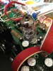
The valves should have a negative grid voltage in relation to their cathodes. The grids are connected to ground via grid-leak resistors. The anodes are supplied via current mirrors which are balanced up by a further current mirror, supplied by 48v. The cathodes are supplied by I'm not sure what kind of circuit, some kind of gain control possibly, which runs off the -15v supply. So anyway, check these +48 and -15 volt supplies. You can confirm the current mirrors are ok by checking the voltage across each of the 10k emitter resistors. They should be about the same.
If the whole thing is simply not giving any output it's most likely that power is not getting to one of the stages. The first thing you should check is that each stage has power. Check the op-amp power pins individually too - a cracked trace will stop the juice getting through.