Hello all,
I hope everyone is having a wonderful May!
Just a quick question/project I was hoping someone wouldn’t mind lending some of their thoughts on, please.
So I’ve a couple of; 12v 4 pin RGB 120mm PC fans that I would like to install in my networking cabinet. One of the cables on the fans is a 12vDC lead with a molex connector on the end. There is a second cable on the fans that is the RGB cable for the LEDs.
To power the fans I will simply cut the end and wire it to a 12vDC power adaptor. (This is not represented in the attached diagram)
Ordinarily to power/control the RGB lights on the fans, you would use a controller. However, I would love to be able to do away with the controller and wire the fans to simply use a few toggle switches. Also, it makes for a very simple fun little project.
Now to the question;
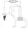
If I cut the end of the RGB wire that has the connector and then wire everything in the below configuration, would this work, or should I be wiring or using a different method? What I’m hoping to achieve is the ability to switch on or off the following colours using a toggle switch: red, green, blue, magenta & cyan.
Switch materials:
12v wire from the 4pin RGB connector > SPST (On – Off) > 12VDC wire from power adaptor.
Red Colour:
Red wire from 4pin RGB connector > SPDT (On – Off – On) > Ground wire from 12vDC power adaptor
Blue Colour:
Blue wire from the 4pin RGB connector > SPDT (On – Off – On) > Ground wire from 12vDC power adaptor
Green Colour:
Green wire from the 4pin RGB connector > SPST (On – Off) > Ground wire from 12vDC power adaptor
Magenta Colour:
Red & Green wire from the 4pin RGB connector > DPDT (On – Off – On) > Ground wire from 12vDC power adaptor
Cyan Colour:
Blue & Green wire from the 4pin RGB connector > DPDT (On – Off – On) > Ground wire from 12vDC power adaptor
Not too sure if the above circuit would even work, but I’d love to hear everyone’s opinion or ideas.
I’ve made a very simple diagram using Word. This might help to explain my idea better.
The idea was inspired by “ZedsTech101” from Youtube.
Many thanks in advance for any feedback or assistance!")
P.S. First time if attempted wiring that is this involved? I have only made a couple of simple on/off switches for 12vDC, so I do apologise in advance for any incorrect terms.
P.P.S. Apologies also if the question is posted in an incorrect place.
I hope everyone is having a wonderful May!
Just a quick question/project I was hoping someone wouldn’t mind lending some of their thoughts on, please.
So I’ve a couple of; 12v 4 pin RGB 120mm PC fans that I would like to install in my networking cabinet. One of the cables on the fans is a 12vDC lead with a molex connector on the end. There is a second cable on the fans that is the RGB cable for the LEDs.
To power the fans I will simply cut the end and wire it to a 12vDC power adaptor. (This is not represented in the attached diagram)
Ordinarily to power/control the RGB lights on the fans, you would use a controller. However, I would love to be able to do away with the controller and wire the fans to simply use a few toggle switches. Also, it makes for a very simple fun little project.
Now to the question;
If I cut the end of the RGB wire that has the connector and then wire everything in the below configuration, would this work, or should I be wiring or using a different method? What I’m hoping to achieve is the ability to switch on or off the following colours using a toggle switch: red, green, blue, magenta & cyan.
Switch materials:
- 2x SPST On – Off
- 2x SPDT (On – Off – On)
- 2x DPDT (On – Off – On)
12v wire from the 4pin RGB connector > SPST (On – Off) > 12VDC wire from power adaptor.
Red Colour:
Red wire from 4pin RGB connector > SPDT (On – Off – On) > Ground wire from 12vDC power adaptor
Blue Colour:
Blue wire from the 4pin RGB connector > SPDT (On – Off – On) > Ground wire from 12vDC power adaptor
Green Colour:
Green wire from the 4pin RGB connector > SPST (On – Off) > Ground wire from 12vDC power adaptor
Magenta Colour:
Red & Green wire from the 4pin RGB connector > DPDT (On – Off – On) > Ground wire from 12vDC power adaptor
Cyan Colour:
Blue & Green wire from the 4pin RGB connector > DPDT (On – Off – On) > Ground wire from 12vDC power adaptor
Not too sure if the above circuit would even work, but I’d love to hear everyone’s opinion or ideas.
I’ve made a very simple diagram using Word. This might help to explain my idea better.
The idea was inspired by “ZedsTech101” from Youtube.
Many thanks in advance for any feedback or assistance!
P.S. First time if attempted wiring that is this involved? I have only made a couple of simple on/off switches for 12vDC, so I do apologise in advance for any incorrect terms.
P.P.S. Apologies also if the question is posted in an incorrect place.