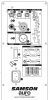
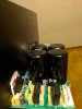
Hi, I'd love some help diagnosing a problematic speaker. I have a Samson Auro D415 Speaker that is having its clip/peak light (7 in diagram) come on intermittently, even with no input plugged in and with gain/level knob (4 in diagram) set to 0.
On the healthy speaker, when I turn power on the peak light comes on for 10 seconds, then turns off and the speaker works normally. On the unhealthy speaker, sometimes the peak light stays on indefinitely. If I try resetting it without jostling the speaker, I sometimes get the light to come off, but if I leave the speaker on for a while the peak light will come on, even with no output or gain. If I set the unhealthy speaker up to with input and bring the level up a bit, behavior is the same - it will stop playing sound at some point when the gain light has come on. It does not seem related to bumping the speaker or bass vibrations.
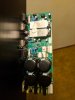
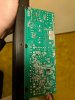
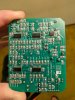
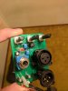
I've taken out the preamp and power amp boards, and I can't see anything amiss - all components look good and even solder points look good as far as I can tell. I have some basic electronics knowledge and a meter, any suggestions on what to look for next, or even how to tell for sure if it's the preamp board or power amp? I've attached the schematics as well. Let me know if I can provide any more info. Thanks in advance for any pointers!
On the healthy speaker, when I turn power on the peak light comes on for 10 seconds, then turns off and the speaker works normally. On the unhealthy speaker, sometimes the peak light stays on indefinitely. If I try resetting it without jostling the speaker, I sometimes get the light to come off, but if I leave the speaker on for a while the peak light will come on, even with no output or gain. If I set the unhealthy speaker up to with input and bring the level up a bit, behavior is the same - it will stop playing sound at some point when the gain light has come on. It does not seem related to bumping the speaker or bass vibrations.
I've taken out the preamp and power amp boards, and I can't see anything amiss - all components look good and even solder points look good as far as I can tell. I have some basic electronics knowledge and a meter, any suggestions on what to look for next, or even how to tell for sure if it's the preamp board or power amp? I've attached the schematics as well. Let me know if I can provide any more info. Thanks in advance for any pointers!
")
