Continue to Site

Welcome to our site!

Electro Tech is an online community (with over 170,000 members) who enjoy talking about and building electronic circuits, projects and gadgets. To participate you need to register. Registration is free. Click here to register now.

  • Welcome to our site! Electro Tech is an online community (with over 170,000 members) who enjoy talking about and building electronic circuits, projects and gadgets. To participate you need to register. Registration is free. Click here to register now.

power transistor mosfet Question

Status
Not open for further replies.
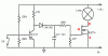
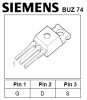
In the diagram below, how would you connect the BUZ74. I'm not familiar with the MOSFETs. I see where they have 3 prongs on the mosfet itself but the diagram shows four.

1. Where is the forth one.. Basically how do you connect one?

2. what does it mean when it says "0v"

3. Will any NPN transister work.?

4. Is that a 4 Meg resister where it says 4M7

Thanks, any advice will be helpfull. Except negitive ones. lol

**broken link removed**

I found it here:
**broken link removed**
 
1) There isn't a fourth prong, the middle (substrate) is internally connected to the bottom (source) inside the case.

2) 0V is the referance point, in this case the positive rail is +V so 0V means the negative terminal of the supply.

3) Yes, most small signal transistors will work.

4) It's a 4.7M resistor or 4.7 million Ohm resistor. It's pretty standard practise to replace the decimal with the suffix. 4k7 is 4.7k, 10R5 is 10.5R and R47 is 0.47R, R is Ohms.
 
That was fast thanks Hero.. I understand all of what you said except point 1.

So the 4.7 and 100K would connect to the center prong? also how do i know which one is base (B), collector (C) and emitter (E).??
 
Look at the datasheet which can be found using a search engine.
 
Yes. IRF510 or IRF540 or IRFZ44N will work, but first, better to use low power lamp (less than 50W) for check. Its safe from blowing up your mosfet when they reach their maximum power dissipation.
 
Warning about this circuit: The dimming takes place by slowly reducing the gate voltage of the NFET as the capacitor discharges through the 4.7megΩ. The dome light in most cars draws more than 1A, which means that as the dimming goes through the half-way point, the NFET will be dissipating more than 4W.

If not heatsinked, it will get quite hot, maybe even damage it. Since you are putting this in a car, bolt the NFET to something metallic in the car. You will need a "mounting kit" consisting of an insulating mica washer, an insulating bushing, a screw, special washer and nut.
 
Last edited:
the "4u7 16V cap." Is that 4.7 cap? If so will a 4.7 25V work
thanks in advance

The voltage rating on a capacitor is the maximum rating so of course you can use a 25V capacitor where a 16V capacitor is specified.
 
I've a friend that has one, never liked reptiles as pets, they're like wall decorations with teeth. Although I have always kind of wanted a snake and a small mice farm to feed it.
 
**broken link removed**


which one is gate, drain, source on the BUZ74?
Why don't you look on its datasheet?

The datasheet shows which pin is which and also shows that it is not suitable to drive a 12V light bulb because it is rated for a very high voltage (minimum of 500V) and has a high voltage loss when it is conducting.
 

Attachments

  • BUZ74 Mosfet.PNG
    BUZ74 Mosfet.PNG
    10.3 KB · Views: 398
Here, I marked the source, drain, and gate on the schematic for you. ;)
 

Attachments

  • fade-in-and-fade-out-effects-to-the.gif
    fade-in-and-fade-out-effects-to-the.gif
    11.1 KB · Views: 1,473
Use a different MOSFET.

I recommend the IRL540 because it's cheap and will do what you want.
 
Status
Not open for further replies.

Latest threads

New Articles From Microcontroller Tips

Back
Top