Electro Tech is an online community (with over 170,000 members) who enjoy talking about and building electronic circuits, projects and gadgets. To participate you need to register. Registration is free. Click here to register now.
Welcome to our site! Electro Tech is an online community (with over 170,000 members) who enjoy talking about and building electronic circuits, projects and gadgets. To participate you need to register. Registration is free. Click here to register now.
I don't see any reason it would not work. I am a little confused about the parts between the bridge and the regulators. I would most likely wire the bridge directly to the regulators, keeping the diode to "direct traffic". Then I would follow each regulator output with one capacitor one load resistor and then a second capacitor. This filter construction would depend on the load (i.e., how clean the output needed to be).
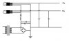
Dunno why you have that odd diode in there,
maybe as a fuse?
Those extra caps you have on the supply sides
of the regulators arent needed,
if they are around 10 mfd, or less, put them
on the outputs of the regulators.
(too big can upset the regs)
Otherwise it seems ok, so long as that R1
is a fairly low value.
If you've built it,
and you're asking why it doesnt work,
then you're in for a question and answer session.
first does either output work?
no.
Do you have mains supply to the transformer?
(AC voltage across primary)
This site uses cookies to help personalise content, tailor your experience and to keep you logged in if you register.
By continuing to use this site, you are consenting to our use of cookies.