Continue to Site

Welcome to our site!

Electro Tech is an online community (with over 170,000 members) who enjoy talking about and building electronic circuits, projects and gadgets. To participate you need to register. Registration is free. Click here to register now.

  • Welcome to our site! Electro Tech is an online community (with over 170,000 members) who enjoy talking about and building electronic circuits, projects and gadgets. To participate you need to register. Registration is free. Click here to register now.

power supply

Status
Not open for further replies.
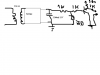
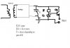
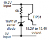
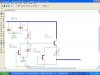
1st: I've got an interview and it was required to design a 15VDC 1 ameprage , i didnt remember that there is a 7815 IC , so i put a 15V zener at the output with series resistor 1k , i tried to increase the current output , i put a PNP transistor after the zener , i know its wrong , but i want to know how my idea can be designed ?

2nd: I've the Art of electronics book , i've just finished my degree in electronics and communications , sometimes i dont understand somethings in it ,does it need a prerequistes ? and do you face that problem too ?
 
Last edited:
yea i know that, we all didnt have a good instructor in electronics he just copy and paste from the reference , and we never learnt anything that is not my problem only all our class ..

could you tell me the answer to the problem above :) ?
 
Nigel, oh you mean the basics about power supply design ? I dont mean that , i mean the final stage of the power supply , i couldnt design it good , i put a 15V zener , but it will deliver with 1k , 15mA , and it was required a 1A power supply , so i put a PNP transistor to increase the current rating , but i know its not correct ...
 
I know the final stage isnt correctly designed
 

Attachments

  • zd.PNG
    zd.PNG
    12.3 KB · Views: 201
You have a 1k resistor from 16V(?) feeding the load.
The transistor keeps the output voltage from rising above 15.6V without a load.
When the load current is more than 0.4mA then the transistor turns off.

You might have used an NPN transistor as an emitter-follower. The circuit would be so simple that I will leave it for you to figure out.
 

Attachments

  • power supply circuit.PNG
    power supply circuit.PNG
    12.6 KB · Views: 181
It wasn't 16V , it was 15V (VCC of the transistor) , but whatever using a PNP or NPN , I cant draw up to 1A , that was my problem in the design is mainting a constant 15V with 1 amp that is why i put that PNP , i dont know what an emitter follower will do in that circuit it will just make the base follow the emitter e.g 15V .
 
You were right to go for an Ic regulator first there are so many avaialble these days which you could have used. Obviously no one can remember all the parts avaialbe that is why we have reference books etc. If you were required to name all parts off the top of your head than fair enough, good interview question :)

Here is what i would have done, fairly basic and i am not sure whther you required it to limit at 1A. The load determines what current you can draw. Also the transformer would have to give a higher secondary voltage than 15V in my modification.

p.s i too am a recent graduate in electronics, i can picture Nigel saying to himself "What the hell are they teaching these kids"
 

Attachments

  • mod.JPG
    mod.JPG
    18.6 KB · Views: 174
Last edited:
A TIP31 NPN transistor as an emitter-follower can supply 1A to a load when its base current is 40mA. A zener diode will keep the base at 16V so that its emitter will be near 15V.

The 15VAC transformer makes 19.2VDC after it is full-wave rectified and filtered.

Use a 68 ohm resistor feeding a 16V/1W zener diode. The base of the TIP31 transistor connects to the zener diode.

The TIP31 transistor will heat with about 4W so it will need a small heatsink.
The output voltage will be +15.4V without a load and will be about +15.2V at 1A.
If the output is shorted then the transistor will get extremely hot.
 

Attachments

  • simple power supply.PNG
    simple power supply.PNG
    4.9 KB · Views: 194
Thanks alot , yea i got it now , but what i really wanted to do is current sink , not a source , that's why i used a PNP transistor , how can i change the design to use it ?
also another question for the design above, why i didnt put a base resistor and a collector resistors ?
 
The 68 ohm resistor is the base resistor for the emitter-follower transistor. It also feeds the zener diode. The zener diode stops the output from rising above about +15.4V.

If you added a collector resistor then it would limit the current and the output voltage would drop.
 
How can you have finished a degree in Electonics and not understand the basics?.

It sounds like a community college. We have one here in town that used to be really bad about supplying qualified instructors. Our basic AC/DC class was taught by a refrigeration instructor. I new more than he did. I was more of a faculty assistant than a student.
 
A TIP31 NPN transistor as an emitter-follower can supply 1A to a load when its base current is 40mA. A zener diode will keep the base at 16V so that its emitter will be near 15V.

The 15VAC transformer makes 19.2VDC after it is full-wave rectified and filtered.

Use a 68 ohm resistor feeding a 16V/1W zener diode. The base of the TIP31 transistor connects to the zener diode.

The TIP31 transistor will heat with about 4W so it will need a small heatsink.
The output voltage will be +15.4V without a load and will be about +15.2V at 1A.
If the output is shorted then the transistor will get extremely hot.

The circuit is speced for 1A. The TIP31 will draw up to 3A. He needs some sort of over-current protection, which will also prevent damage from short circuit. View the attached schematic. Someone else may have an easier method. Also, something I noticed that was inconspicuously missing was a high freq. cap (0.1uF) for RF filtration. Did I miss anything, schematic wise? There is a way to do this using one transistor, but the design escapes me. Other thoughts?

p.s. Please forgive the crude drawing. I'm still getting the hang of Eagle.
 

Attachments

  • power supply.JPG
    power supply.JPG
    83.6 KB · Views: 188
Last edited:
You can. But I'm with Andy257. Why not just use an IC regulator such as the LM350? All that' required is a voltage regulator on the output fed back to the adj. pin. you can still use the over-current circuit using one NPN transistor. It would be a simpler design and probably easier for you to remember. I can supply you the details for the over-current if this is a route you wish to follow.
 
I know man that an IC is better , but that was an interview question ( a challenge) , and i designed it using a PNP and i suspected that it was wrong , so i wanted to know the answer or the correct design using a PNP , got me ? that all happend because i didnt remember that there is a 7815 available ...
 
All you need is an EA that can operate off your rail voltage,pass transistor, a reference and some passives.

Here is a 5.1V nominal LDO I’m building 15 mA max output. The schematic is a bit messy because I’m bouncing between AC simulations for loop gain and transient for load step testing. I’m using a P-FET to minimize ground (Quiescent) current and drop out voltage. V3 is really a TLVH431 reference. You could use the second opamp in the package for current sensing use this with a comparator to shut down the regulator in the event of a sustained OC. You of course have to make sure all components are properly rated for your voltages etc. Anyway the schematic is one possible way of using your desired PNP.

If you have the headroom you are better off using a NPN or depending on available voltages an N-FET. Or as suggested the best solution's a three terminal off the shelf regulator.The data sheets will show how to use a pass Transistor and may have hints for Fold back or basic current limiting.

It’s odd with an EE degree you don’t know how to use an external PASS transistor with off the shelf three terminal regulators 723 ,7800 series etc. Most of these three terminal packages will be thermally limited.
Edit C6 isn't connected to the EA output it should be connected to the bottom of R1.

**broken link removed**
 
Last edited:
Hi Rezer,
If the output is shorted then the poor little 2N3904 transistor in your circuit will try to sink 279mA. Its max allowed current is 200mA and it has hardly any gain above only 100mA.
The 2N3906 transistor will not give it enough base voltage to the 2N3904 so it might conduct 140mA with 10V across it and then burn with the resulting 1.4W.
The 68 ohm resistor also might burn.

Hi Ahmed,
this is a positive supply. Usually the positive side is regulated, not the ground side.

Hi AudioGuru,
Your right about that. However, if you were to use a TIP122 which has higher gain and can saturate with lower base current this would be a better design for my circuit. Using just one 2n3904 transisor with the base/emitter across the current-sense resistor (emitter connected to the DC out and base to the emitter of the series-pass, the collector would go to the base of the series-pass. The 2n3904 would monitor the current, when it conducts, it would divert current from the base of the pass-transistor, thereby limiting it's current output.
I did not redesign the circuit, because ahmedragia21 has made it clear what he was after. I just wanted to explain further.

ahmedragia21,
Yes, I got it. But, evidently, no body got it because your request was not addressed. You stated in your origial post that, "I've got and interview...". Well, here in the states, that's future tense. And remember, my schematic is not the original design, I just modified for over-current sense.

I can get something for you later using a PNP transistor @ 15V/1A (I'm on my break:)).
 
Status
Not open for further replies.

Latest threads

New Articles From Microcontroller Tips

Back
Top