Continue to Site

Welcome to our site!

Electro Tech is an online community (with over 170,000 members) who enjoy talking about and building electronic circuits, projects and gadgets. To participate you need to register. Registration is free. Click here to register now.

  • Welcome to our site! Electro Tech is an online community (with over 170,000 members) who enjoy talking about and building electronic circuits, projects and gadgets. To participate you need to register. Registration is free. Click here to register now.

Power supply for microcontroller relay

Status
Not open for further replies.

edeca

Active Member
I would like to build a temperature sensor that switches on and off a mains supply to keep what I am heating at a set temperature. However, I am wondering where to get power for my micro (a PIC).

I have two main questions:

1) I have seen these fairly cheap: **broken link removed** but can't work them out (I'm assuming that's AC-AC), could this sort of thing work? Or is there a better approach? I'd rather not use batteries or another DC supply if possible, if I already have mains power through the circuit!

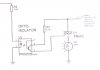
2) Would a relay or TRIAC & opto-isolator be best? The book I am reading suggests a TRIAC which doesn't appear to need a separate DC power supply, other posts online seem to suggest that is desirable for a relay. I will be switching a maximum of 60W, the heat mat I have now is 18W.

Thanks.
 
Hi edeca

The link with the product shows just normal print transformers (and that is AC to AC) you still have to rectify and stabilize the power in order to give it to a IC

a opto coupler and triac is a good solution for swiching AC loads

but a relais does the same but is mechanical and does consumes more energy

How many Watts is the heater element?

Robert-Jan
 
I'd use a relay on the output & to power up the micro circuit I'll definitely use a small transformer.Everything is isolated.

To make it compact I'll use a capacitive TX less power supply for micro & driving a TRIAC output with no any isolation.

Looks like you are building a temperature controlled soldering station :D
 
Last edited:
I have just made something similar, using one of those transformers.

You have to rectify the AC output to DC. The best way is to use 4 diodes or a bridge rectifier (which is just 4 diodes in one box)

You then need to smooth with a capacitor. That keeps the PIC going when the mains voltage drops to zero 100 times each second.

Then you need to regulate with a voltage regulator, such as a 78L05 if you want 5V.

With those little transformers, they have a lot of internal resistance, so the output of the rectifier can be quite large with no load. I found it better to use a full bridge with 4 diodes, rather than half-wave rectifying the two secondary windings, to reduce the voltage drop caused by the internal resistance.
 
Thanks for all the replies. I'm not building a temperature controlled soldering station ;)

The heater I am using is an 18W heat mat, designed for reptiles. I am using it to heat a small enclosure that (fortunately) doesn't contain reptiles. Instead of buying the expensive heat controller, I thought I would look into how to build one. In future I might build a larger enclosure with a larger heater, the biggest is around 60W.

I have found a diagram of what Diver300 recommends here: http://www.kpsec.freeuk.com/powersup.htm#trsr

Diver300's post and that diagram explains it very nicely. I have built 7805 supplies before for DC-DC so am quite happy with that. However I have two further questions if anybody can help:

1) The transformer specification sheet shows 4 connections on the 'stepped down' side, 0 SEC 0 SEC. Which are connected to the bridge rectifier? Why are there two 0 connections?

2) I am assuming that a 50V 1 or 2A bridge rectifier will do, something like **broken link removed** ? I am unsure here though. I assume 50V because that's the minimum and I'll be using a 12V transformer to step down. Power requirements are quite low and the 7805 only does 1A from memory.
 
edeca said:
1) The transformer specification sheet shows 4 connections on the 'stepped down' side, 0 SEC 0 SEC. Which are connected to the bridge rectifier? Why are there two 0 connections?

There are two separate secondary windings. They are isolated and can be connected in series or parallel. The direction is important.

https://www.tpub.com/neets/book7/27b.htm shows a rectification circuit that I have often used. It has the advantage of only having one diode drop but the disadvantage that the more current flows in the windings for less time, giving more voltage drop, especially on small transformers.

edeca said:
2) I am assuming that a 50V 1 or 2A bridge rectifier will do, something like **broken link removed** ? I am unsure here though. I assume 50V because that's the minimum and I'll be using a 12V transformer to step down. Power requirements are quite low and the 7805 only does 1A from memory.

That rectifier would be fine. It is bigger than you need but you won't find anything else much cheaper. You won't even need 1A. The biggest load will be the relay that switches the heater.

12Vac is too big. You want a 6V transformer, parallel the outputs (connect 0 to 0 and sec to sec). That will give you something like 8Vdc loaded, maybe 12Vdc with no load, so there is plenty for the regulator to work with. If you fit a larger voltage of transformer, you just throw away more power in the regulator and then you may need a heat sink for it.
 
Thanks for all the replies. I'm not building a temperature controlled soldering station ;)

The heater I am using is an 18W heat mat, designed for reptiles. I am using it to heat a small enclosure that (fortunately) doesn't contain reptiles. Instead of buying the expensive heat controller, I thought I would look into how to build one. In future I might build a larger enclosure with a larger heater, the biggest is around 60W.

I have found a diagram of what Diver300 recommends here: Power Supplies

Diver300's post and that diagram explains it very nicely. I have built 7805 supplies before for DC-DC so am quite happy with that. However I have two further questions if anybody can help:

1) The transformer specification sheet shows 4 connections on the 'stepped down' side, 0 SEC 0 SEC. Which are connected to the bridge rectifier? Why are there two 0 connections?

2) I am assuming that a 50V 1 or 2A bridge rectifier will do, something like **broken link removed** ? I am unsure here though. I assume 50V because that's the minimum and I'll be using a 12V transformer to step down. Power requirements are quite low and the 7805 only does 1A from memory.


Hi Edeca,

You can use a 120V - 12V step down transformer (12 - 0 - 12) along with 2A bridge and 470mfd filter. Feed this to 7805 metal package and from here u can drive the PIC directly. Bypass the 12V line directly to the relay coil and drive it with a transistor. You will get 12V relay with 10A contact, this is enough to switch your load.

If you still want reduce the cost and remove the bulky transformer....there is another way ....Graveyard design. Here you can step down the 120V line using a 5W resistor and drive the rectifier section.

Hope this help....
 
Thanks again for your message. With regard to load, if I use an optoisolator & triac, surely there wont be much? A MOC3020 seems to be a DIP package with the isolator and triac inbuilt and can take 240v no problem. It is also fairly cheap. I assume I can connect the LED side to the PIC and the other side straight to the same incoming mains as the transformer.

However, if I ever design a PCB for this, how do I run 240v through it? Are there recommendations for size of track etc?

Your help is greatly appreciated, power electronics sure is turning out to be more to think about! :)


Hi edeca,

You cant drive your load directly with MOC out. You need to drive it through another triac because Igt max=50mA. Please refer the datasheet....

Regarding PCB track, you can run the AC lines in one side and keep all the low voltage line other side. There are some IPC standard for track thickness and isolation. I have enclosed the same for your ref....

Hope this will help you to overcome the obstacle....
 

Attachments

  • moc3020.pdf
    102.9 KB · Views: 244
  • Document2.pdf
    14.8 KB · Views: 355
Thanks Rajaneesh! I realised that about the output after :(

Is there any real difference then between a MOCxxxx and an isolator with a transistor in, which is what the book I have here describes. I can then couple this with a minimum 400V 1.5A triac (e.g. BTA10 which is 10A) to drive the load?

Your document about the PCB is very useful. Does this mean that you have to run the tracks on separate sides? Or that it is recommended? I have only ever dealt with single sided boards before.

I will draw a circuit later and post a list of parts I think I will use. If anybody can tell me which bits are wrong, I will be grateful :)
 
Last edited:
I've had a look now, could you advise me whether any of these are unsuitable?

Transformer: **broken link removed**
Diode bridge: **broken link removed**
Triac for driver circuit: **broken link removed** - I think 0.8A at 230V should provide 192W, which is more than enough

I can't seem to find optocouplers at this supplier though, are any or the ones in this category suitable: **broken link removed** ? Or would a relay be much easier?

Thanks for all your help.
 
Last edited:
You obviously need a smoothing capacitor and a voltage regulator.

5V is enough to turn on the Triac, but if you isolate with an opto isolator you need some type of non-isolated supply to feed the gate of the Triac.

You can't get power through an opto isolator. Its output just appears as a switch and if you want to block 230 V ac you need a switch rated to 400 V dc
 
You obviously need a smoothing capacitor and a voltage regulator.

That's fine, I'm used to using those. I hope I can calculate the correct values and buy ones rated for the right voltages.

5V is enough to turn on the Triac, but if you isolate with an opto isolator you need some type of non-isolated supply to feed the gate of the Triac.

You can't get power through an opto isolator. Its output just appears as a switch and if you want to block 230 V ac you need a switch rated to 400 V dc

This is where I am confused, hence lots of questions, sorry. The book I have here shows the mains voltage straight through the coupler. I couldn't find any parts rated for this. Are there any? Or is mains through the coupler the wrong way to do it? I have attached a small scan from the book showing just this portion of the circuit.

If I need a separate supply through the coupler to the triac gate, I don't see the advantage over a relay which would also need a separate supply. Thus I'm not sure which to use as I could just connect up a relay with a protective diode and forget all about optocouplers.

Can I take the separate supply from before the regulator? If so, would you recommend a relay instead of a triac?

Thanks again for your reply.
 

Attachments

  • IMG.jpg
    IMG.jpg
    24 KB · Views: 340
That's fine, I'm used to using those. I hope I can calculate the correct values and buy ones rated for the right voltages.

For the smoothing capacitor, the site at Power Supplies suggests the following equation for 10% ripple:

C = (5 * Io) / (Vs * f)

470uF is suggested in many circuits. Vs is easy to calculate, 0.7v drop per diode:

Vs = 12 - (0.7 * 2)
Vs = 10.6

I am not entirely sure about Io, is this assumed to be 2A if the bridge rectifier is 2A? What else does it depend on?

So for 240v 50hz input, what value capacitor would be required to smooth the transformed/rectified 12v?
 
Mains voltage onto the opto coupler would work, if you can find an opto-coupler that is rated to the peak main voltage.

I suggest an Omron G3VM-351B, available from RS or Mouser. In fact, there are similar devices that would switch the current you want without using a triac at all.

I also have doubts whether the circuit in the example would work. When the main voltage goes negative, that would give a negative voltage on the opto isolator, which would probably cause breakdown.

Any voltage that feeds the gate of the triac has to be relative to T1 of the triac, so there has to be another connection to T1 of the triac. That means that there cannot be isolation between the whatever feeds the gate voltage and the triac. That means that you can't take the supply from the same transformer windings.

The whole reason to use a transformer is to have isolation so that the micrcontroller cannot have any dangerous voltages on it.

On your capacitor calculation, you would do better to parallel the two tranformer secondaries.

Although the nominal voltage is 6V, that is at full load and it is the RMS voltage so the peak voltage is 1.4142 times a big, and bigger still at low loads. The current is whatever the circuit take, not 2A. The transformer is only rated at 0.25A for both windings in parallel.

The resistance of the transformer is quite large on these small transformers so the output voltage will drop a lot as more current is taken.

You want to aim for about 0.5V ripple, so the capacitor has to be larger than:-

I / 0.5 / 2f so if you are on 50 Hz mains the answer is 5000:mu:F, so you should maybe use a 4700uF 16V capacitor. If the current that the microcontroller takes is less, you could get away with more ripple so a much smaller capacitor would do, but 4700:mu:F, 16V is much smaller and cheaper than the tranformer anyhow.
 
Mains voltage onto the opto coupler would work, if you can find an opto-coupler that is rated to the peak main voltage.

I suggest an Omron G3VM-351B, available from RS or Mouser. In fact, there are similar devices that would switch the current you want without using a triac at all.

I'll start a new thread about this later.. understanding the AC to DC is confusing enough! I shouldn't have posted two questions in one thread here.

On your capacitor calculation, you would do better to parallel the two tranformer secondaries.

Thanks, I was adding 6v+6v instead of remembering it is 6v RMS when in parallel. I now understand your calculation for the capacitor value at 0.25A which is what I wanted.

I now have a circuit drawn up (to make a board from later), it is attached.

When converting DC to DC capacitors are used on the 7805 input and output. Do I still need these? I don't think I need the one on the input side as the 4700uF is doing the same job.. but I'm not sure. That should be my last question before buying the parts and blowing a few fuses!

If you have any comments on the circuit that would be great, I'll remove the capacitors later if they aren't needed.
 

Attachments

  • Full-transformer.jpg
    Full-transformer.jpg
    147.4 KB · Views: 288
When converting DC to DC capacitors are used on the 7805 input and output. Do I still need these? I don't think I need the one on the input side as the 4700uF is doing the same job.. but I'm not sure.

If wires were had no impedance and capacitors had no inductance, then the 100 :mu:F would be pointless, but in the real world, you should always have capacitors close to the input of a regulator, and the inductance should be low. That means that you should have a small (therefore low inductance) capacitor right beside the regulator. For that reason, the 100 :mu:F could help.
 
Status
Not open for further replies.

Latest threads

New Articles From Microcontroller Tips

Back
Top