Continue to Site

Welcome to our site!

Electro Tech is an online community (with over 170,000 members) who enjoy talking about and building electronic circuits, projects and gadgets. To participate you need to register. Registration is free. Click here to register now.

  • Welcome to our site! Electro Tech is an online community (with over 170,000 members) who enjoy talking about and building electronic circuits, projects and gadgets. To participate you need to register. Registration is free. Click here to register now.

power supply for micro controller

Status
Not open for further replies.

Parth86

Member
I don’t know how the component are connected in this power supply please any one help me to understand how the component are connected

This PCB contain two circuit

Power supply

Programmer circuit
I have attached image

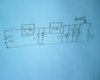
Power supply circuit component

12v battery connected to battery connector . battery connector connected to on/off switch. On / off switch connected to bridge rectifier IC w104br , after rectifier IC don’t know which one capacitor c10 or c13 connected to the output of rectifier and voltage regulator IC 7085 connected to output of filter capacitor

First I don’t know which one is one capacitor is connected C10 or C13?
 

Attachments

  • 8051development - Copy.jpg
    8051development - Copy.jpg
    17.7 KB · Views: 233
The data sheet says the "recommended" cap values are 0.33uF on the 12v side and 0.1uF on the 5v side

This should give you a clue.... Have you a multimeter??
actually I searched for power supply and I got this Image I wantto make power supply myself In this circuit I don't know which one capacitor is connected first I want to make layout first after that I want to soldering on PCB
 
I wantto make power supply myself In this circuit I don't know which one capacitor is connected first I want to make layout first after that I want to soldering on PCB

lm7805.gif

Straight from the data sheet of an LM7805 regulator... You start with this..
 
battery+battery connector+on/off switch+bridge IC+1000/60 Electrolytic Capacitors+0.33uF Ceramic Capacitors+7085 IC+ 0.33uF Ceramic Capacitors

now I have led,resistor , reset switch , jumper, how they connect together
 
Are you making the board in your first post???
battery+battery connector+on/off switch+bridge IC+1000/60 Electrolytic Capacitors+0.33uF Ceramic Capacitors+7085 IC+ 0.33uF Ceramic Capacitors
bridge IC+1000/60.. What is this.. If it's battery powered why do you need a bridge? This is so you can plug in a wall adapter that outputs 12ac.
 
check out this its paper work
12v dc battery +battery connector+bridge IC+ capacitor+voltage regulator IC+capacitor+variable resistor+jumper (5 volt for controller+ 5v for programmer circuit )+reset switch+current limiting resistor +LED indicator
 
hello again , I need power supply circuit for micro controller and sensor circuit. I have 12v dc battery and I need 5v for micro controller and 5v for sensor circuit

component
battery- 12v dc
battery connector
switch- on/off
bridge Ic- 2w10G
C1 capacitor- 1000/25 volt Electrolytic Capacitors
C2capacitor - 22 pf/50 volt Ceramic Capacitors
regulator Ic-708 5v/1amp
C3 capacitor - 22 pf/25 volt Ceramic Capacitors
R1 variable resistor
reset switch
jumper J1
jumper J2
R2fixed resistor
indicator - LED
I have attached Image
 

Attachments

  • IMG_0056.JPG
    IMG_0056.JPG
    62.1 KB · Views: 202
The 7805 needs to have the ground pin connected... For what purpose is the variable resistor... What are the J1 and J2 for.

This is all you need to supply 5v from a 12 v battery
 

Attachments

  • 5v ps.bmp
    18.9 KB · Views: 185
The 7805 needs to have the ground pin connected... For what purpose is the variable resistor... What are the J1 and J2 for.

This is all you need to supply 5v from a 12 v battery
J1 and J2 are jumper J1 is used for micro controllers supply and J2 is used for sensor supply . variable resistor is used adjust the resistance.
see post #1 I am trying to make that type of power supply
 
Status
Not open for further replies.

Latest threads

New Articles From Microcontroller Tips

Back
Top