Triode
Well-Known Member
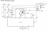
So I have this board I'd like to use, it looks to be exactly the same as the one [**broken link removed**]
My best guess is that I would want a small toroid transformer that supplies 2 outputs at 15 VAC. The amp chip is rated at 1.5W and the smallest torroid I can find in 3.2VA so even if I need the full power of the amp I think it will work.
The data sheet for the TPA amp IC says the two 15V inputs can be tied together. Do I really need two, or does the separate power supply really do anything? Again it's kind of a moot point because they all seem to have two taps anyway. I don't know if tying them together into one 15V supply is a problem.
I found [this transformer], it's cheap, but seems like it would work
"Power:3.2VA
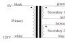
Input:2 x 115V
Output 2x 15V"

Just to be sure, I wire it with 3 and 5 together into one AC supply pole, and 4 and 6 together into the other? Then to my amp (I think) I would wire 12 and 14 to 0V input, 13 to one of the 15V inputs and 11 to the other? I don't think there is any reason I would want them to be out of phase since that would supply 30V, but maybe for all I know the board is meant to work that way.
Thanks for helping. Sorry if any of these are stupid questions, I just want to be sure I don't blow up anything.
My best guess is that I would want a small toroid transformer that supplies 2 outputs at 15 VAC. The amp chip is rated at 1.5W and the smallest torroid I can find in 3.2VA so even if I need the full power of the amp I think it will work.
The data sheet for the TPA amp IC says the two 15V inputs can be tied together. Do I really need two, or does the separate power supply really do anything? Again it's kind of a moot point because they all seem to have two taps anyway. I don't know if tying them together into one 15V supply is a problem.
I found [this transformer], it's cheap, but seems like it would work
"Power:3.2VA
Input:2 x 115V
Output 2x 15V"
Just to be sure, I wire it with 3 and 5 together into one AC supply pole, and 4 and 6 together into the other? Then to my amp (I think) I would wire 12 and 14 to 0V input, 13 to one of the 15V inputs and 11 to the other? I don't think there is any reason I would want them to be out of phase since that would supply 30V, but maybe for all I know the board is meant to work that way.
Thanks for helping. Sorry if any of these are stupid questions, I just want to be sure I don't blow up anything.

")

