Hi All-
This is my first post so be gentle")
I have always been intrigued by electronics, and now that I am semi-retired, I have time to actually do something I've wanted to for a long time.
For background, I used to subscribe to Popular Electronics in the small format, and built many Heathkits, so I'm not a total ignoramus in electronics, I just have no formal training.
The project is replacing all my wall light switches with touch plates. After several months of experimenting and several designs, I have learned a lot but I'm at the point where I just can't seem to figure out how to accomplish what I want given the constraints I have placed on the project. The touch switch itself is not a problem, the qprox qt118 works beautifully.
The Constraints-
1. Low power. There are over 30 switches and they will be on all the time.
2. Low cost. Again, there are over 30 of these.
3. Low waste current. These will be in a small enclosed box in the wall, so cooling is a problem.
4. Small size. Has to fit in a standard switch box with to six or more 14 guage romex cables in and out, etc.
Additionally, the power needs to be referenced to the neutral so that separate circuits in three and four way switch setups can signal with a pulse across the third wire to trigger a flipflop.
The problem is the power for the qprox and a d-type flipflop. I try to simulate all the conditions that could occur like brown-outs, momentary power losses of varying duration, noise, and so on. I definitely don't ever want all the lights in the house to turn on if the is a momentary power loss of any duration.
The qprox wants the startup power applied at a minimum of 100 volts/second rate. The flipflop will sometimes trigger unexpectedly if the voltage is applied too slowly.
The qprox only draws 10 micro amps at 3 volts, and the cmos TC7W74F flipflop even less, so I need a very low current power supply.
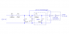
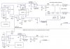
Input is standard 120 volts AC. After many different deigns, to best meet the design criteria, I have found a simple diode to 220K resistor to 47uf cap and 4.7 volt zener provides a good 3.6 volts for the chips. Remember that the power needs to be referenced to the neutral wire so I can communicate over the third wire between switch boxes on 3-way setups, so I can't use a bridge. This draws about 400 micro amps from the wall. Transformers were just too bulky and expensive. I have to dump 98% of the voltage as waste heat, but at half a milliamp, it doesn't seem to be a problem. The problem is that the voltage comes up too slowly and drops too slowly during a momentary outage to make the chips happy. I added a resistor across the capacitor to drop the voltage, and decreased the input resistor but still too slow and raised the waste current.
So what I need is a simple, cheap circuit that will apply voltage to the chips quickly and remove it quickly based on whether their is input voltage. My problem is that this circuit will need it's own power supply with the same constraints, which puts me in vicious circle I don't know how to get out of. If the design uses even less than 400 micro-amps, since I only actually need about 50 microamps for the chips, that would be great too!
I know the answer is somewhere but I just don't know enough to google with the right criteria.
Any help will be greatly appreciated.
-Jim
This is my first post so be gentle
I have always been intrigued by electronics, and now that I am semi-retired, I have time to actually do something I've wanted to for a long time.
For background, I used to subscribe to Popular Electronics in the small format, and built many Heathkits, so I'm not a total ignoramus in electronics, I just have no formal training.
The project is replacing all my wall light switches with touch plates. After several months of experimenting and several designs, I have learned a lot but I'm at the point where I just can't seem to figure out how to accomplish what I want given the constraints I have placed on the project. The touch switch itself is not a problem, the qprox qt118 works beautifully.
The Constraints-
1. Low power. There are over 30 switches and they will be on all the time.
2. Low cost. Again, there are over 30 of these.
3. Low waste current. These will be in a small enclosed box in the wall, so cooling is a problem.
4. Small size. Has to fit in a standard switch box with to six or more 14 guage romex cables in and out, etc.
Additionally, the power needs to be referenced to the neutral so that separate circuits in three and four way switch setups can signal with a pulse across the third wire to trigger a flipflop.
The problem is the power for the qprox and a d-type flipflop. I try to simulate all the conditions that could occur like brown-outs, momentary power losses of varying duration, noise, and so on. I definitely don't ever want all the lights in the house to turn on if the is a momentary power loss of any duration.
The qprox wants the startup power applied at a minimum of 100 volts/second rate. The flipflop will sometimes trigger unexpectedly if the voltage is applied too slowly.
The qprox only draws 10 micro amps at 3 volts, and the cmos TC7W74F flipflop even less, so I need a very low current power supply.
Input is standard 120 volts AC. After many different deigns, to best meet the design criteria, I have found a simple diode to 220K resistor to 47uf cap and 4.7 volt zener provides a good 3.6 volts for the chips. Remember that the power needs to be referenced to the neutral wire so I can communicate over the third wire between switch boxes on 3-way setups, so I can't use a bridge. This draws about 400 micro amps from the wall. Transformers were just too bulky and expensive. I have to dump 98% of the voltage as waste heat, but at half a milliamp, it doesn't seem to be a problem. The problem is that the voltage comes up too slowly and drops too slowly during a momentary outage to make the chips happy. I added a resistor across the capacitor to drop the voltage, and decreased the input resistor but still too slow and raised the waste current.
So what I need is a simple, cheap circuit that will apply voltage to the chips quickly and remove it quickly based on whether their is input voltage. My problem is that this circuit will need it's own power supply with the same constraints, which puts me in vicious circle I don't know how to get out of. If the design uses even less than 400 micro-amps, since I only actually need about 50 microamps for the chips, that would be great too!
I know the answer is somewhere but I just don't know enough to google with the right criteria.
Any help will be greatly appreciated.
-Jim
Last edited: