Continue to Site

Welcome to our site!

Electro Tech is an online community (with over 170,000 members) who enjoy talking about and building electronic circuits, projects and gadgets. To participate you need to register. Registration is free. Click here to register now.

  • Welcome to our site! Electro Tech is an online community (with over 170,000 members) who enjoy talking about and building electronic circuits, projects and gadgets. To participate you need to register. Registration is free. Click here to register now.

Power Supply for 115 vdc motor

Status
Not open for further replies.

kloomis

New Member
I just bought this motor on eBay:
**broken link removed**

Or, use this TinyURL, if that link doesn't work for you:
**broken link removed**

Now I need to get or build a power supply for that. I'd prefer a variable power so I can vary the speed of the motor.

I am not even sure how to get started so any suggestions will be greatly appreciated.

Thanks,
Ken
 
I just bought this motor on eBay. Now I need to get or build a power supply for that. I'd prefer a variable power so I can vary the speed of the motor. I am not even sure how to get started so any suggestions will be greatly appreciated.

That's a Bodine motor. Search for Bodine on this forum (I just tried it and it works) and you'll find out how to access their motor handbook, which shows you how to control it, how to brake it, etc. Everything you could want is there.
 
1/50th hp is 15w, so it's 130 mA at 115v, a ~900 Ω load.
120vacrms with a full wave bridge gives ~120vdc.

Once you rectify,
if you don't need control down to zero or high torgue at low speeds you could use series resistors. A 15w, 120v bulb in series with this motor will you give slightly more than half power.

And, I've seen app notes that boost an LMxxx regulator's voltage handling capability using an external transistor.
 
Thanks for the replies. I do have some follow up questions:

saturn1bguy:
I took your advice and downloaded the Bodine-Electric Small Motor, Gearmotor and Control handbook. At 258 pages, that will be quite the read and I am sure quite helpful. I was wondering how you determined that the motor I purchased was a Bodine motor. I couldn't find any motors on their site that matched any of the identifying numbers that I could read off of the specs plate.

Willbe:
When you say "full wave bridge" would this work for that:

**broken link removed**

I have found some designs for power supplies that start with a bridge rectifier, but they all seem to use capacitors. I assume the capacitors smooth out the pulses. If I wanted to do that, what type and value of capacitor would I need to use?

And, if I did want to make this variable voltage to adjust the speed of the motor, could I use this:

**broken link removed**

Thanks for any further help on this.

Ken


BTW: The project I am working on is a yard decoration of a Santa on an elliptical exerciser with a sign that says, "Please do not feed the Santa!" The motor will provide the animation of Santa exercising.
 
You don't need any smoothing capacitors for a motor. I would strongly advise against using them because they will increase the RMS voltage delivered to the motor to more than 120V which could blow it up.

Using a variable resistor is a rubbish way to implement speed control because it's very inefficient and the torqure is severely reduced at low speeds.

Use PWM or even phase control on the AC side.

Don't forget that you need to connect the motor's case to earth for safety reasons.
 
the yellow label says: Bodine Electric Motor
 
I was wondering how you determined that the motor I purchased was a Bodine motor. I couldn't find any motors on their site that matched any of the identifying numbers that I could read off of the specs plate.

If it looks like a duck, and quacks like a duck...

As it's an older motor, you won't find your model type (NSH-12R) on their web page. You'd have to call them. I have units newer than yours that don't appear there. It looks like NSH refers to a shunt type motor, the R = a right angle shaft. Here's one of my Bodine's, an NCI-12R:
 

Attachments

  • Bodine Motor.JPG
    Bodine Motor.JPG
    18.8 KB · Views: 2,281
  • Bodine Motor (2).jpg
    Bodine Motor (2).jpg
    24.5 KB · Views: 1,298
Last edited:
Willbe:
When you say "full wave bridge" would this work for that:

**broken link removed**

It's a 15A bridge; you only need a half-amp or so. Solder some 1N4004s from hosfelt.com. 8 cents each. No heat sink needed.

Yard decoration means use an isolation transformer. Public safety and all that.
 
Last edited:
My bad on the 15w bulb; it will give about 1/4th power.

For the prototype, I'd substitute larger and larger bulbs in series with the iso. xformer, the diode bridge and the load until you find a workable value. Measure the current through and the voltage across the bulb; this is your resistor value and wattage.

5 ea. of Hosfelt's part #56-966 @$6 ea., properly phased, makes your iso. xformer. 4 ea. might even do it, at this low current.
 
5 ea. of Hosfelt's part #56-966 @$6 ea., properly phased, makes your iso. xformer. 4 ea. might even do it, at this low current.

I don't know what to do with those, but I'm guessing the inputs are in parallel and the outputs are in series. Is that right?

What does "properly phased" mean and how to I be sure that happens?

Here is what I had in mind:

**broken link removed**

or, something similar. The description of another isolation transformer that I am looking at says, "115 to 115 AA and rated at 150VA." Will that work?

I am also looking for a PWM motor speed controller, but I can't seem to find one rated high enough to handle the 115 VDC of this motor. Any suggestions for that?

Thanks for all the help.

Ken
 
You don't need any smoothing capacitors for a motor. I would strongly advise against using them because they will increase the RMS voltage delivered to the motor to more than 120V which could blow it up..
I did some searching with Google and found a site that explains RMS. It gave this as the formula for RMS:
Vrms = 0.7 × Vpeak​
and
Vpeak = 1.4 × Vrms​
for 120 Vpeak that would mean a Vrms of 84 V. Wouldn't adding smoothing capacitors bring the Vrms closer to the 115 V rating for the motor?

Don't forget that you need to connect the motor's case to earth for safety reasons.
If I run ground straight thru the power supply and attach it to the motor's case, will that suffice for connecting it to 'earth'?

Thanks for bearing with me on this stuff. I am really trying to learn as much as I can from these projects I am doing.

Ken
 
The mains voltage is measured in RMS not peak.

If the nominal mains voltage is 120V, the peak will be nearly 170V. If a large capacitor were connected to the output of the rectifier to make the ripple negligible the 170V steady DC voltage would cause the motor to overheat.

Without the capacitor the RMS voltage across the motor would be 120V minus the insignificant rectifier losses which wouldn't do it any harm.
 
I think this is the way that some of our old lab pumps, with 115VDC motors, were wired. Fairly good speed control and torque.

Ken
 

Attachments

  • 115VDCMotorSpeedControl.gif
    115VDCMotorSpeedControl.gif
    7.4 KB · Views: 960
Thanks for the replies.

I think I have found an isolation transformer that will work. The specs on the box read:

Isolation
Transformer
115V to 115V
150V.A. 60 CY.
Electrostatically
Shielded​
Am I right to assume that this will work for the isolation transformer?

I also think I have found a motor speed control. I am looking at one of these:
**broken link removed**
Here is a link to the spec sheet for that style of controller:
Do you think that will work for the speed control?

I was planning on using the 1N4004 diodes in a bridge rectifier arrangement, but I think this speed controller will take care of that for me. Is that assumption correct?

Thanks again for any help.

Ken
 
I was planning on using the 1N4004 diodes in a bridge rectifier arrangement, but I think this speed controller will take care of that for me. Is that assumption correct?

From the datasheet, though I can't read the schematic, it looks like you are correct.

Ken
 
An isolation transformer is a good idea but isn't needed if you earth the frame of the motor and all other exposed metal parts.
 
An isolation transformer is a good idea but isn't needed if you earth the frame of the motor and all other exposed metal parts.

I am still confused about this 'earth' thing. To me that means I buy a copper clad stake that's about 5 foot in length and drive it into the ground somewhere near the motor and connect the case of the motor and all other metal parts to it.

Is there another meaning for "connecting to earth" that I don't know about?

As an update, here are the pieces I have ordered to build the "Exercising Santa" display:
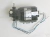
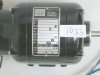
Motor:
**broken link removed**

Isolation Transformer:
**broken link removed**

Motor Speed Control:
**broken link removed**

When I get all these, I'll put together a schematic and ask your opinion before I wire everything up.

Thanks for all your help with this.

Ken

BTW: Did you ever have one of the "I coulda had a V-8" moments where you slap yourself on the forehead when you realize the opportunity you just missed. I just had one of those this morning.

Last week I gave away a treadmill that I no longer needed. I had purchased it for $10 at a yard sale and it worked pretty well, but the monitoring electronics didn't work, so I thought I'd pass it along. Then, this morning while searching eBay, I found this:

**broken link removed**

Duh!?!?!

And that even uses standard pulleys and belts instead of the #25 chain & sprockets on that motor I bought.
 
Last edited:
I mean protective earth or ground.

I don't know the colour of the protective earth cable in your country but here in Europe it's green and yellow srtiped.

If you don't use an isolation transformer, you need to connect the moto case to protective earth because if the insulation on the winding fails the case will float at mains potential which would pose a shock hazard.

Another way to avoid the requitement for a protective earth connection is to put the motor in plastic case and use plastic gears so the output shaft isn't electrically connected to the motor's frame.

EDIT:

The neutral conductor of the mains is connected to earth at either the distribution board or where it enters your property. This means that if you touch the phase conductor you can get a lethal shock. An isolation transformer eliminates this risk by isolating the neutral from the earth, meaning you have to touch both line conductors simultaneously to get a shock.

I strongly recommend you read the Wikipedia article and that if you don't understand the concept of a safety earth connection then don't do this for your own safety.
**broken link removed**)
 
Last edited:
I mean protective earth or ground.
Now, 'ground' I understand.

I don't know the colour of the protective earth cable in your country but here in Europe it's green and yellow srtiped.
Ground is usually indicated with a green wire.

If you don't use an isolation transformer, you need to connect the moto case to protective earth because if the insulation on the winding fails the case will float at mains potential which would pose a shock hazard.
Since I have already purchased the isolation transformer, and I expect to be using this motor set up to animate other lawn decoration, I think it'll be best to go ahead and include it.

I strongly recommend you read the Wikipedia article and that if you don't understand the concept of a safety earth connection then don't do this for your own safety.
**broken link removed**)
Thanks for that link. It really did clear things up for me. I feel fairly confident most of the time when I am working with electricity and electrical circuits. I just always like to be doubly safe whenever I hear something that I don;t understand, like 'earth' vs 'ground.'

Thanks again.

Ken
 
Status
Not open for further replies.

New Articles From Microcontroller Tips

Back
Top