Continue to Site

Welcome to our site!

Electro Tech is an online community (with over 170,000 members) who enjoy talking about and building electronic circuits, projects and gadgets. To participate you need to register. Registration is free. Click here to register now.

  • Welcome to our site! Electro Tech is an online community (with over 170,000 members) who enjoy talking about and building electronic circuits, projects and gadgets. To participate you need to register. Registration is free. Click here to register now.

power supply circuit

Status
Not open for further replies.

Gaston

Member
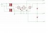
could you guys take a look at this circuit and tell me if the five volt part will work. its a 24 volt center tap so i should get 12 volts from the center. and with only one diode i should only get helf of the wave which would be six volts or a little over 8 to the peak once the cap is charged.i hope to have enough to overcome the dropout of the regulator. could i get by with any lower valued capacitors on either side of the regulator? i just put 4700 because thats what i have. the five volts is for a isd1110p chip and thats all. does it look ok?

POWER-SUPPLY.png
 
Your circuit will give +-32.5VDC not +-12V which will blow up anything rated for 12V.

You only need one 12V-0-12V transformer with an LM7912 and an LM7812 to give you +-12VDC.
 
the + - 35 volts is for an amp. i also need 5 volts to run an ic. thats why im trying to use the center tap rather than buying another transformer.
 
i just noticed the diode is in backwards. my main concern is if the cap before the 7805 is going to smooth out the choppy wave enough for the regulator to do its job.
 
Gaston said:
the + - 35 volts is for an amp. i also need 5 volts to run an ic. thats why im trying to use the center tap rather than buying another transformer.
There's nothing wrong with that but why not use one 24V-0-24V transfromer rather than two smaller transformers?

i just noticed the diode is in backwards. my main concern is if the cap before the 7805 is going to smooth out the choppy wave enough for the regulator to do its job.
That depends on what current you want to draw.
 
I find it had to believe that two transformers were cheaper than one.

30mA should be no problem, even a 470:mu:F capacitor would do let alone a 4,700:mu:F capacitor.
 
Your 5V won't have the same 'common' as the amplifier. If you try to connect the commons together the smoke will leak out. Will that be a problem?
 
You're right.

I didn't think the 5V was to power something that interfaced with the amplifier.

Tha can easilly be resolved though.

Put the 5V supply betwee 0V and the centre tap of the top transformer with the diode at the poitive input to the regulator.
 
the smaller transformers were cheaper because i did a lot of searching for a bargain and they were pretty cheap...but no 48volt ct. if i were to order out of a cataloge im sure it would be cheaper than two though.
 
There's a much better way to hook up the transformers and rectifiers. Hook the two transformers as a 48VCT arrangement. Use the CT of 48VAC as COMMON. Use ONE bridge rectifier. Connect the AC input of the bridge to the two outside AC lines from the transformer. The DC outputs of this bridge are approximately +/- 32VDC.

Connect a second bridge to the two CT windings. The DC outputs of this bridge are +/- 16VDC. Use the +16VDC as the input to your 7805.
 
Gaston said:
the smaller transformers were cheaper because i did a lot of searching for a bargain and they were pretty cheap...but no 48volt ct. if i were to order out of a cataloge im sure it would be cheaper than two though.
I haven't seen a 48V centre tapped transformer before but I've seen plenty of transformers with twin 24V secondaries that could be connected in series for form a 48V CT transformer.
 
mneary said:
Connect a second bridge to the two CT windings. The DC outputs of this bridge are +/- 16VDC. Use the +16VDC as the input to your 7805.

It is coming 32.5VDC isn’t it if he takes the two CT loops?

For Gaston

But your two transformers is not a good solution. If I want to power your project I will simply buy a 28V-0-28V – 12V transformer without thinking money because need to do a proper design. But the voltage will be little high to the amp! No problem – More sound
 
money is a big issue here. i have to build twenty of these. plus i already bought the transformers
 
Don't the place you bought them from accept returns?
 
Gaston. Like this:
 

Attachments

  • Supply.JPG
    Supply.JPG
    65.5 KB · Views: 177
Last edited:
Oh, I just thought that since most transformer primaries and outer secondary wires are not colour coded for proper phasing, that Gaston should measure the total secondary voltage once the circuit is built, and that it is ~48VAC. The circuit will work either way, it's just that wired the wrong way, the rectifiers will put out 60HZ DC instead of 120HZ. (or 50 instead of 100 in UK). Filtering is easier the higher the freq.
 
Last edited:
Status
Not open for further replies.

Latest threads

New Articles From Microcontroller Tips

Back
Top