yohanevindra
New Member
we hav this project to do which consits of several digital devices which need 5V and a PIC minimal board which needs regulated 5V or direct 9V supply...
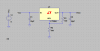
our plan is to supply the device with 9V and then supply the board with that same 9V and then construct a power regulator circuit. we bought the LM1084IT-5.0 power regulator since our requirement is 5V output with a maximum of 3A at about 1 second intervals. ive done a simulation on LT spice, and the output is about 5.3V..i got not output current, but when i put a 1ohm resistor as the lod it gave me about 5A. does this mean the circuit is doin what we need it to be doin?so we can use it?I'm attaching the schematic of the circuit.
our plan is to supply the device with 9V and then supply the board with that same 9V and then construct a power regulator circuit. we bought the LM1084IT-5.0 power regulator since our requirement is 5V output with a maximum of 3A at about 1 second intervals. ive done a simulation on LT spice, and the output is about 5.3V..i got not output current, but when i put a 1ohm resistor as the lod it gave me about 5A. does this mean the circuit is doin what we need it to be doin?so we can use it?I'm attaching the schematic of the circuit.
")
