Continue to Site

Welcome to our site!

Electro Tech is an online community (with over 170,000 members) who enjoy talking about and building electronic circuits, projects and gadgets. To participate you need to register. Registration is free. Click here to register now.

  • Welcome to our site! Electro Tech is an online community (with over 170,000 members) who enjoy talking about and building electronic circuits, projects and gadgets. To participate you need to register. Registration is free. Click here to register now.

power MOSFET

Status
Not open for further replies.
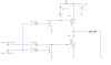
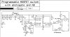
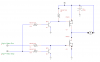
Alright, so I've been working on I guess what you could call an advanced solid state switch for a high current motor. The input switch allows for a user interface and the photogate allows for the microcontroller to monitor the position of the motor. Because the motor needs to stop immediately once the microcontroller tells it to, I am trying something which I believe is called active braking (or AB).

Here's my problem.

the current p-type MOSFET's cost is just a little high for what it is intended to do in this case .

Does anyone know of a replacement p-type MOSFET that would work in this case and can handle atleast 30A (I've had measured current spikes as high as 20A from this thing)
 

Attachments

  • Programmable MOSFET +Photogate+AB.jpg
    Programmable MOSFET +Photogate+AB.jpg
    100.9 KB · Views: 975
Your PFET will be ON even when the output of the PIC is high because the PIC will only output 5V when high. You MOSFET supply voltage is 8.4V leaving 3.4V on the gate when the PFET is supposed to be OFF. BTW, you've mixed up the symbols for the NFET and PFET.
Use a gate driver IC so you can use two NFETs and isolate the logic supply from the motor supply properly.
 
Because this thing isn't mean't for high-speed switching (it will be the control board within an Airsoft AEG) and the motor will really only be on in one direction, could an optocoupler and corresponding pull down resistor be put in place to isolate the mosfet's from the PIC?

Sorry, I'm just having a hard time understanding what the driver IC actually does.
 
The FET driver IC would allow you to use 2 NFETs instead of a PFET and an NFET. It can also provides a higher gate drive voltage for the FETs. It also provides a delay so that both FETs don't conduct during switch over.
Did you get what I meant by, "Your PFET will be ON even when the output of the PIC is high because the PIC will only output 5V when high."?
 
The p-channel Mosfet is a logic level mosfet similar to the IRL1404Z.

Instead of using the FET driver IC, would it be possible to run two IRL1404Z's directly from the PIC using the unused I/O with one controlling the motor and one becoming the motor's load as soon as the power to the motor has been cut?
 
One way of doing it would be this way:

motor-png.31857

The the PIC needs to insert a short delay (Say 100uS) between Motor Run and Motor Stop. This is because there is a small switching delay in the circuitry where both FETs would be on if this delay wasn't present. Q2 takes care of the case where the PIC has gone nuts and attempted to both stop and run the motor at the same time. A high/low side driver chip would take care of all that. The above is a cheap, simple, low speed switching circuit.
 

Attachments

  • Motor.png
    Motor.png
    11.1 KB · Views: 2,786
I was hoping to use the N-channel for the motor to be powered because I know that the N-channel mosfets usually have a lower drain to source resistance that the P-channel.

would the attached circuit work as is or should I have an inverter between the output/MOSFET so that the gate is at 8.4v (similar to yours the collector of the NPN transistor would be connected to the 8.4v source through a 1k resistor.
 

Attachments

  • Programmable MOSFET +Photogate+AB.jpg
    Programmable MOSFET +Photogate+AB.jpg
    179.1 KB · Views: 1,382
You'd need the extra NPN transistor for the same reason I gave before:
Your PFET will be ON even when the output of the PIC is high because the PIC will only output 5V when high. Your MOSFET supply voltage is 8.4V leaving 3.4V on the gate when the PFET is supposed to be OFF.
With my circuit, if you want the NFET to power the motor, you can simply connect the motor to the +8V rail instead of ground and swap the inputs like so:
motor-png.31906
 

Attachments

  • Motor.png
    Motor.png
    10.1 KB · Views: 3,132
Last edited:
(sorry for the late reply, I haven't had access to the internet in a few days)

Cool, thankyou for the help.

I've got just one more question now though. Do both of the MOSFET's require a protection diode to prevent backup current from destroying the PIC?
 
No. Both MOSFETs contain a built in diode from source to drain (Indicated by the arrow on the schematic symbol). It is a relatively slow diode, but plenty fast enough for the slow speed switching your circuit will be doing.
The more likely path for PIC destruction would be via the 5V regulator so make sure that is properly bypassed. Also make sure that the high current paths feeding the FETs and motor are separated from the signal paths of the PIC. It is OK to have a common ground and V+ but make sure they are joined at the power source and that you don't daisy chain the motor ground feed via the PIC circuitry ground on it's way to the battery.
 
Last edited:
Status
Not open for further replies.

Latest threads

New Articles From Microcontroller Tips

Back
Top