mading2018
Member
I starting a new thread now. I know how to get the power dissipation, taken the average value of the instaneous power with the thermometer probe over a component. But how come that the losses shows different each time? If I compare the circuit of an interleaved PFC and a boost PFC, where the recitfiers are exactly the same with the same input, they still give different values...why is that?
I thinking also to skip to measure the capacitors in the circuit in the simulation, cause they shows just too high values, from 100 W up to 500 W..maybe it is not accurate to measure capacitors..
I thinking also to skip to measure the capacitors in the circuit in the simulation, cause they shows just too high values, from 100 W up to 500 W..maybe it is not accurate to measure capacitors..
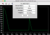
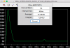
") but I notice now that if I run the simulation for a longer time, the power dissipation for capacitor looks much better.
but I notice now that if I run the simulation for a longer time, the power dissipation for capacitor looks much better.


