I continuing work on a project of mine you can read about here:
**broken link removed**
I'm trying to add support for the Nintendo Gamecube. The Gamecube uses a single open collector line for communication, with each bit taking 4us: if its a high bit, is 1us low, 3us high while a low bit is 3us low, 1us high. now I think I've got the code for reading and writing this way set, but of course its not working on the real hardware.
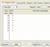
What I'd like to figure out is how to use a waveform of some sort on the computer for simulation and debugging. I'd also like the ability to see the wafeform the PIC responds with. I can see the 'Stimulus' and 'workbook' menu items in MPLAB using MPSIM, but I cannot find any usefull information on HOW to use them, or if they even do what I am wanting. What I really want is something like ModelSIM from the Xilinx WebPack, but for PICs.
Given my situation of needing both input and output stimulus, what sort of simulation and debugging options do I have, and where are some easy instructions on starting their use?
**broken link removed**
I'm trying to add support for the Nintendo Gamecube. The Gamecube uses a single open collector line for communication, with each bit taking 4us: if its a high bit, is 1us low, 3us high while a low bit is 3us low, 1us high. now I think I've got the code for reading and writing this way set, but of course its not working on the real hardware.
What I'd like to figure out is how to use a waveform of some sort on the computer for simulation and debugging. I'd also like the ability to see the wafeform the PIC responds with. I can see the 'Stimulus' and 'workbook' menu items in MPLAB using MPSIM, but I cannot find any usefull information on HOW to use them, or if they even do what I am wanting. What I really want is something like ModelSIM from the Xilinx WebPack, but for PICs.
Given my situation of needing both input and output stimulus, what sort of simulation and debugging options do I have, and where are some easy instructions on starting their use?