Continue to Site

Welcome to our site!

Electro Tech is an online community (with over 170,000 members) who enjoy talking about and building electronic circuits, projects and gadgets. To participate you need to register. Registration is free. Click here to register now.

  • Welcome to our site! Electro Tech is an online community (with over 170,000 members) who enjoy talking about and building electronic circuits, projects and gadgets. To participate you need to register. Registration is free. Click here to register now.

Polarity switching relays

Status
Not open for further replies.

bigal_scorpio

Active Member
Hi to all,

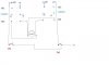
I am just in the process of making a motor controller for a 7amp 24v DC motor so I roughed out this design.

I need 2 momentary switches to control the motor but obviously I cannot afford to have both relays energised at the same time, so I decided to run the opposite relays coil from the normally closed relays contact, hopefully preventing both being energised together.

My problem is where to put the back EMF diodes!

Any ideas would be appreciated so dig in guys.

Al

My circuit:-
 

Attachments

  • Relay1.JPG
    Relay1.JPG
    13.1 KB · Views: 527
Last edited:
Hi,

no digging necessary. :)

This circuit can never cause a short. The motor will receive VDD and ground with changing polarity depending on the operated switch. If both switches are operated simultaneously the motor will receive VDD at each terminal causing it to stop rapidly. (fast braking)

The same applies when no switch is depressed. In that case both terminals are tied to ground with the same braking action.

If soft braking (free running) is desired you might add limit switches in both ground connections towards the relays (relay terminals 12 and 22).

Since you can't kill a transistor caused by EMF (using switches) you only need one fast recovery diode connected between VDD and ground. The MR850 can stand 50V at 3A.

You might want to choose a higher voltage rating of the diode - so select an MR852 for 200V.

Boncuk
 

Attachments

  • CW-CCW.gif
    CW-CCW.gif
    11.5 KB · Views: 186
Last edited:
Hi mate,

Thanks, that is a much better design than mine, I can see the benefits immediately! :)

As to the diodes, the biggest I have to hand are 1N4007, will they do the job?

Thanks again.......Al
 
Hi again,

Just another thought, I was planning on adding the diodes originally to reduce arcing at the relay contacts. Maybe there is another way of prolonging the life of the contacts that I don't know about? Any suggestions?

Thanks.........Al
 
Hi scorpio,

a 1N4007 can stand up to 1,000V but is a slow rectifier diode with a current flow of max 1A.

Fast recovery diodes have a recovery time of 100ns.

So a 1N4007 can only be a temporary solution.

I measured an EMV-voltage of 120V with a 24VDC solenoid. So I guess 24VDC relays will produce about the same hight of EMV.

To protect the relay contacts you might use WIMA FKP-2-10nF (630VDC/250VAC). They are manufactured with a pitch of 5mm (use 5.08mm=0.2inch) directly connected to both (NO - COM and NC - COM) relay terminals.

Using 16A rated relays you might omit protective caps. (Check out Finder relays type S66)

Regards

Boncuk
 

Attachments

  • CW-CCW-1.gif
    CW-CCW-1.gif
    13.9 KB · Views: 183
Last edited:
Status
Not open for further replies.

Latest threads

New Articles From Microcontroller Tips

Back
Top