Continue to Site

Welcome to our site!

Electro Tech is an online community (with over 170,000 members) who enjoy talking about and building electronic circuits, projects and gadgets. To participate you need to register. Registration is free. Click here to register now.

  • Welcome to our site! Electro Tech is an online community (with over 170,000 members) who enjoy talking about and building electronic circuits, projects and gadgets. To participate you need to register. Registration is free. Click here to register now.

PNP darlington Pair calculation understanding

Status
Not open for further replies.

Kranthikkenoch

New Member
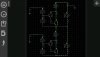
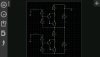
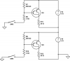
I have a 20ohms discharge resistor connected to my PNP darlington pair. I have simulated the circuit in my mobile (every circuit app).please find the attachment for circuit. But here I'm unable to understand how the PNP transistors are turned on. Please help me understand this circuit. Also while I'm ordering the components online and select Maximum collector current should be (+1A or -1A)
 

Attachments

  • 2.jpg
    2.jpg
    93.7 KB · Views: 114
  • 1.jpg
    1.jpg
    92 KB · Views: 118
  • darlington PNP.png
    darlington PNP.png
    18 KB · Views: 99
Conventional current flows from the + through the emitter, out through R8 or R10, then through the switch(s) to ground, this turns on the trans, pulling the collector close to +.
 
Status
Not open for further replies.

Latest threads

New Articles From Microcontroller Tips

Back
Top