Continue to Site

Welcome to our site!

Electro Tech is an online community (with over 170,000 members) who enjoy talking about and building electronic circuits, projects and gadgets. To participate you need to register. Registration is free. Click here to register now.

  • Welcome to our site! Electro Tech is an online community (with over 170,000 members) who enjoy talking about and building electronic circuits, projects and gadgets. To participate you need to register. Registration is free. Click here to register now.

PNP BJT....Collector and emitter currents very different

Status
Not open for further replies.

Flyback

Well-Known Member
Hello,

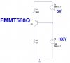
In the attached common base schematic, the collector current should equal the emitter current. However, collector current is very low at 800uA.
In this configuration, and with the FMMT560Q PNP transistor, is there any situation where , say, high leakage current would mean that collector and emitter currents were not almost equal to each other?

FMMT560Q datasheet
https://www.diodes.com/assets/Datasheets/FMMT560Q.pdf
 

Attachments

  • PNP.jpg
    PNP.jpg
    35.8 KB · Views: 130
The collector current is almost the same as the emitter current which is also very low.
 

Attachments

  • common base transisor.png
    common base transisor.png
    115.2 KB · Views: 112
Thanks, though we are worried that when the PNP saturates, the collector current will be much less than the emitter current.
 
If you run a simulation with the two voltage sources changing there is very little difference between the collector and emitter currents. Try adding some leakage in the sim and see if the difference becomes greater than whatever you consider acceptable.
 
Thanks again, and I mean, the PNP in the schematic of the top post cannot saturate because its Base-Collector junction cannot get forward biased in that schematic and setup.
 
Thanks, though we are worried that when the PNP saturates, the collector current will be much less than the emitter current.
How can the PNP saturate? You show NO input signal. Is V1 the input signal? What is its voltage range?
An NPN works exactly the same as a PNP in that circuit except the polarities are reversed.
 
With the resistors you chose, V1 has to be >58V for Q1 to saturate.

73.png

Notice the difference between I(R1) and I(R2) = -Ib(Q1). Note the increase of V(c)
 
Flyback

Conversely, if V1=5V, then as R1 is reduced below 421Ω, Q1 saturates:

73a.png
 
Status
Not open for further replies.

Latest threads

New Articles From Microcontroller Tips

Back
Top