Hi ,
can any one let me know how current flows in PN junction when it is forward biased and reverse biased?
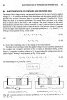
As of i know when PN junction is connected in forward bias the depletion layer decreases and when it is connected in reverse biase the depletion layer increases. I am able to understand upto this. I am not able to undrstand how current flows?
pls let me know.
thanks in advance
can any one let me know how current flows in PN junction when it is forward biased and reverse biased?
As of i know when PN junction is connected in forward bias the depletion layer decreases and when it is connected in reverse biase the depletion layer increases. I am able to understand upto this. I am not able to undrstand how current flows?
pls let me know.
thanks in advance