I wanted to make this: How to Convert a Computer ATX Power Supply to a Lab Power Supply - wikiHow so I could have a power supply when I work on electronics.
I then saw this: How to Add Variable Voltage to Your ATX Based Bench Power Supply - wikiHow so I bought all the necessary components. Currently I have everything working. If I turn the pot and put my meter across the output of the variable voltage (the positive probe on my multimeter) and the -12V (for the neg prob) I get a range from 1.2V to 21.5V. So far I am happy.
I thought why not put a meter in my box (I created a wooden box to give me more room) so I don't have to get my multimeter out each time I change the voltage. I found this: https://www.electro-tech-online.com/threads/digital-voltmeter-power-supply.85574/ and it sounded like the exact same thing I was doing.
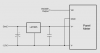
My problem is that I bought this meter PM-1029B: Circuit Specialists Inc. - LED 5V Common Ground Panel Meter (PM-1029B) but I am having a problem connecting it to the variable circuit. The 5V and ground power the meter fine (it all lights up). You can see where they should connect by looking at this photo: https://circuitspecialists.com/images/PM-1029Bback.jpg. It is the V+ (5V) and the V- (ground) at the bottom left of the image.
Above that is the VIN and the GND connections for the meter. I connected the VIN (output of the variable section) but when I connect the GND to the -12V the whole power supply and everything shuts off. If I wait about a minute I can turn it all back on but the second I re-connect the GND part of the meter it shuts off again.
Any ideas on what might be causing the problems? I am able to submit any photos if needed?
I then saw this: How to Add Variable Voltage to Your ATX Based Bench Power Supply - wikiHow so I bought all the necessary components. Currently I have everything working. If I turn the pot and put my meter across the output of the variable voltage (the positive probe on my multimeter) and the -12V (for the neg prob) I get a range from 1.2V to 21.5V. So far I am happy.
I thought why not put a meter in my box (I created a wooden box to give me more room) so I don't have to get my multimeter out each time I change the voltage. I found this: https://www.electro-tech-online.com/threads/digital-voltmeter-power-supply.85574/ and it sounded like the exact same thing I was doing.
My problem is that I bought this meter PM-1029B: Circuit Specialists Inc. - LED 5V Common Ground Panel Meter (PM-1029B) but I am having a problem connecting it to the variable circuit. The 5V and ground power the meter fine (it all lights up). You can see where they should connect by looking at this photo: https://circuitspecialists.com/images/PM-1029Bback.jpg. It is the V+ (5V) and the V- (ground) at the bottom left of the image.
Above that is the VIN and the GND connections for the meter. I connected the VIN (output of the variable section) but when I connect the GND to the -12V the whole power supply and everything shuts off. If I wait about a minute I can turn it all back on but the second I re-connect the GND part of the meter it shuts off again.
Any ideas on what might be causing the problems? I am able to submit any photos if needed?