Continue to Site

Welcome to our site!

Electro Tech is an online community (with over 170,000 members) who enjoy talking about and building electronic circuits, projects and gadgets. To participate you need to register. Registration is free. Click here to register now.

  • Welcome to our site! Electro Tech is an online community (with over 170,000 members) who enjoy talking about and building electronic circuits, projects and gadgets. To participate you need to register. Registration is free. Click here to register now.

pls explain this circuit to me

Status
Not open for further replies.

chopper

New Member
i post this circuit in a another thread but the response i get is mostly telling me this circuit has a lot of power loss.(maybe i did not state clearly my intention in the previous post)

the main concern i post this circuit is i want to understand how the output of the circuit can appear as a waveform(sine wave or square wave is not my concern) with a positive and negative cycle.

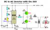
what is the main factor or process that made the output of the the 555 timer which is a a square wave that alter from 0-12v to come out with a waveform that has positive and negative cycle at the secondary side of the transformer?

how this happen?and why?

is the purpose of the LC circuit use to shape the squarewave to a sine wave and has nothing to do with the positive and negative cycle thing?

Please do explain it to me .Thanks a lot.
 

Attachments

  • 20082365544_DC to AC Inverter.JPG
    20082365544_DC to AC Inverter.JPG
    82.7 KB · Views: 237
chopper I'm gonna try again. The circuit pulses the primary coil of the transformer with 0 and 12 volt pulses. The secondary of the transfomer is electrically no connected to it, the energy is transfered in the magnetic field, this means the secondary has no ground reference. When the primary of the transformer is going from 0-12 volts you will get a positive swing on the secondary and when it goes from 12 volts to 0 you will get a negative swing on the secondary. It's called transformer isolation.
 
I think the important thing to realize here, and Scaedwian is trying to help you understand, is that "ground" or "zero volts", and "positive" vs "negative" is a human conceived point of reference whose meaning is derived literally only when connected to an "Earth ground" circuit. A transformer isolates the circuit on the secondary side from any and all ground references, unless of course the designer chooses to establish another ground by tapping the secondary. This is what a center tapped power supply does with respect to Mains AC, at least in North American electronics. A recent thread here actually helped me realize a misunderstanding concerning transmission line power and transformers.

So, in your circuit everything is floating because it is battery powered. The secondary is an AC waveform, not much different than what an AC generator produces. The cycle of current is sinusoidal, so the oscillation is a 360 degree cycle that mimics the mechanical rotation of the generator rotor converting magnetic energy to electrical. A polarized magnetic body in rotation has two poles, "north" and "south" or "+" and "-", and in a full cycle these poles will pass the neutral point where their influence is balanced TWICE. With that neutral point as a reference, we can establish our zero volt or "ground" point for all the electrically connected circuits afterward. However, any currents induced through a transformer beyond the source will be floating.

This is basically what your circuit is doing, on the primary side you have an oscillator creating this waveform, inducing it through a transformer. In a free floating AC waveform such as you are creating, we can consider the neutral point where polarity change is 90 degrees from either extreme to be zero volts, with, in your case, 6 volts swing to the positive and 6 volts to the negative, for a total of 12 volts.
 
Hi chopper,


The circuit works as follows...


Before the circuit is turned on, the capacitor C8 is discharged.
When the circuit is first turned on, the output is low and because C8 is discharged
nothing much happens. Soon the output switches high, which drives Q3 into
conduction. As Q3 conducts it's emitter voltage rises fairly fast and this means
C8 (+) terminal rises fast, and because it rises fast C8 (-) terminal also rises
quite quickly, which puts a positive pulse at the upper primary lead of the output
transformer TR1. That's basically how it gets it's positive pulse, but now something
else starts to happen...
The pulse stays high for a while, and so current flows through C8 into TR1 primary,
which means C8 starts to charge up with it's (+) lead positive and it's (-) lead
negative. All the while the pulse is high some voltage appears across the transformer
primary and some begins to appear across the cap because it charges up somewhat.

Next the output of the 555 goes low, which starts the negative half cycle.
With the 555 output low and C8 having a positive voltage at it's (+) terminal,
Q4 begins to conduct emitter to collector, and that puts the (+) terminal of
C8 at approximately ground potential (close to 0v). With C8 (+) terminal now
at ground and we know that C8 was charged somewhat, that means that the
(-) terminal of C8 now has a negative voltage with respect to ground.
That negative voltage appears at the output transformer's primary, and since
the other lead is still connected to ground that means it now has a negative
voltage across it's primary.

Thus, the cycle started with a positive voltage across the primary and later
a negative voltage across the primary and that's basically how it gets both
positive and negative voltages across the primary.

The cap stores charge in the form of a voltage so it subtracts from the output
of the 555 and that's how the primary can go negative.


Another way to understand the basic operation is to replace C8 with a small battery
of maybe 1/2 the supply voltage and then observe how the primary goes negative
when the output of the 555 goes to zero and the PNP conducts. The positive
terminal of the battery would be forced to ground, so the negative terminal would
of course be negative with respect to ground so again the transformer gets it's
negative pulse that way.
 
This topic is on two or three other websites.

The inverter has so many voltage losses that its output voltage drops very low when it has a load and is too high without a load.
The inductor is way too small to filter its square-wave output into a sine-wave.

It is a copy of this one:
 

Attachments

  • 555 inverter.PNG
    555 inverter.PNG
    12.4 KB · Views: 231
Hello again,

I have to agree that the inductor doesnt do much. It could be said that it
forms part of a 3kHz BP filter, but that filter would be too flat to do anything useful.
The only guess is that it helps to reduce RFI by limiting the rise and fall times of the
pulses.
 
Status
Not open for further replies.

Latest threads

New Articles From Microcontroller Tips

Back
Top