Electro Tech is an online community (with over 170,000 members) who enjoy talking about and building electronic circuits, projects and gadgets. To participate you need to register. Registration is free. Click here to register now.
Welcome to our site! Electro Tech is an online community (with over 170,000 members) who enjoy talking about and building electronic circuits, projects and gadgets. To participate you need to register. Registration is free. Click here to register now.
Look at its datasheet!
1) Its max continuous current is only 600mA so it can drive only very small motors.
2) With a 600mA motor its total max saturation voltage loss is 3.6V.
3) Its total max supply current is 84mA when it is doing nothing.
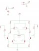
i tested the new H-Bridge but it doen't work well , i noticed that one of the TIP 41 is going too hot .....and the motor work even without any signal.....i'll post you my schematic and tell me why that had happened?
i tested the new H-Bridge but it doen't work well , i noticed that one of the TIP 41 is going too hot .....and the motor work even without any signal.....i'll post you my schematic and tell me why that had happened?
Maybe your motor draws much more than 3A. Measure its resistance. If it is 4 ohms then its max current from 12V is 3A.
Only one signal can be high at a time. If both are high then there will be smoke.
When a signal is at ground then the BC337 is turned off and it turns off the associated TIP41 and TIP42. Therefore when both signals are low then none of the transistors are turned on.
Your LED is connected to the supply voltage. It doesn't affect the transistors.
1) Does the input signal go to 0V when it is turned off?
2) Does the input signal go up to near +5V when it is turned on?
3) What are the resistor values?
4) Does the motor draw only 3A max? Measure its resistance.
The circuit might need protection diodes across the power transistors.
anyway i'll prepare aother PCB may be that is the reason and i'll try a very small motor.
something else i need to ask about :
in the LM338 datasheet i have found an application for 12 volt battery charger using this regulator and ic lm301A .... what is the advantages of using this circuit ?
i mean what is the differance between this circuit and the simple one which use just the lm338 and a potentimeter.
ya i know this chip but it has at least one disadvantage with my application..it's MIN supply voltage is 18 and i'm going to use just one battery on my robot with 12 Volts.
i'm trying to make a new H-Bridge with Auduioguru idea ...i know it's correct design...so it will work i'm sure
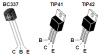
i'm using in this h-bridge a new compontents except the two TIP 41 transistor ...... can i test this TIP 41 with the AVO meter like the usual transitor?
This site uses cookies to help personalise content, tailor your experience and to keep you logged in if you register.
By continuing to use this site, you are consenting to our use of cookies.