Continue to Site

Welcome to our site!

Electro Tech is an online community (with over 170,000 members) who enjoy talking about and building electronic circuits, projects and gadgets. To participate you need to register. Registration is free. Click here to register now.

  • Welcome to our site! Electro Tech is an online community (with over 170,000 members) who enjoy talking about and building electronic circuits, projects and gadgets. To participate you need to register. Registration is free. Click here to register now.

please look over my RF circuit

Status
Not open for further replies.

NleahciM

New Member
Hi - so I'm horrible with RF stuff. So I thought it'd be best to post my design before I send this bugger off to Olimex.

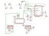
Anyways - here's the schematic:

It has a bunch of parts that I would expect much of anybody to be familiar with. I also just realized that I have the wrong transistor in there - I think I must have started this schematic before I was very comfortable with making my own parts. That should be a 2N4401. Either way - the pinout is the same.
This is the RLP-434A: **broken link removed**
Notice that I'm using the Holtek HT-12D (**broken link removed**) exactly as it is shown used in the RLP-434A datasheet.
The other part that I would not expect anybody to be familiar with is a really odd little bugger - the BPS 200-2-14-50:
It is essentially just a board mountable power supply.

I expect I don't need to explain too much what this board does - but I will just in case. It is designed to switch the relay between it's two positions when it receives a specific signal from the RLP-434A which sends the signal to the HT-12D which decodes it, sending a pulse to the latch, which will then switch, switching the relay.

Hopefully that made sense.

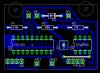
OK with all that out of the way, here's my board:

So - how does it look?
 
Last edited:
So - how does it look?

Well you won't be needing to worry about stray capacitances and inductances on this, as all of the RF stuff is on the RX module; although it is always a good idea to keep leads and traces short as possible.
 
I don't know what you are planning to switch with the relay, but HT-12's have another 3 data latches, why not use them? ie..Bell, whistle and self destruct :)
 
chiba said:
I don't know what you are planning to switch with the relay, but HT-12's have another 3 data latches, why not use them? ie..Bell, whistle and self destruct :)
I just realized - HT-12Ds have latched outputs - don't they? I wonder if the latch is even necessary... I feel like I protoboarded it and it was - but that was probabaly 6 months ago. I'll try that out tomorrow.

About the extra outputs - I've been thinking I might just run them to a pin header, just in case I ever need them...
 
zachtheterrible said:
So - how does it look?

Well you won't be needing to worry about stray capacitances and inductances on this, as all of the RF stuff is on the RX module; although it is always a good idea to keep leads and traces short as possible.
What about the ground plane? I put it on top - with the idea that the antenna would be on top as well. Is this a good idea?

Also - should I be connecting earth ground to DC ground?
 
Yeah, i don't think a ground plane would hurt. Im not sure how well it will help in the way of range. I have a 433mhz module and got @ least 200 meters with it without a ground plane.

Not sure what you mean by connecting earth to DC ground? I think they're the same thing.

I forgot to look, but do you have decoupling capacitors?
 
zachtheterrible said:
Yeah, i don't think a ground plane would hurt. Im not sure how well it will help in the way of range. I have a 433mhz module and got @ least 200 meters with it without a ground plane.

Not sure what you mean by connecting earth to DC ground? I think they're the same thing.

I forgot to look, but do you have decoupling capacitors?
No - I haven't added those in yet... Wasn't sure if I needed anything besides maybe a tanalum on the HT12D and the RLP-434A.

About earth and ground and whatnot - notice that the BPS module is a 5V DC supply with an AC input. What I'm wondering is if I should be connecting AC ground to DC ground, or if I should leave them seperate. I'm not very knowledgeable when it comes to AC stuff which is why I thought it'd be best if I asked.
 
Everything looks correct to me, assuming you are using the BIAS thing correctly. I have made several circuits using the HT12D and the the Laipac Receiver, so I am familiar with those. BTW, did you make the HT12D and Laipac Receiver stuff in Eagle or was it in a stock library?

I used eagle for my board, but I just used a generic 18 pin DIP for the HT12D and pin headers for the RF receiver. If those aren't stock libraries, I would be interested in using them, if that's cool with you.

Here is my schem/board...if your interested. Notice mine is used to enable/disable a 555 timer that then powers a dc motor.
 

Attachments

  • schem_816.jpg
    schem_816.jpg
    42.3 KB · Views: 1,063
  • board_196.jpg
    board_196.jpg
    103.9 KB · Views: 850
There's a Holtek library at cadsoft.de. The Laipac parts (along with the Bias part, and the relay) I all made myself in a custom library.
 
Status
Not open for further replies.

New Articles From Microcontroller Tips

Back
Top