Continue to Site

Welcome to our site!

Electro Tech is an online community (with over 170,000 members) who enjoy talking about and building electronic circuits, projects and gadgets. To participate you need to register. Registration is free. Click here to register now.

  • Welcome to our site! Electro Tech is an online community (with over 170,000 members) who enjoy talking about and building electronic circuits, projects and gadgets. To participate you need to register. Registration is free. Click here to register now.

PLEASE IS THER ANYONE WHO CAN HELP US?LARGE SEGMENT DISPLAY

Status
Not open for further replies.

Jay Duluguin

New Member
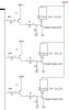
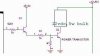
Im sorry to interrupt for anyone cause i really/badly need your help but please advice us what IC could be used to transform logic output signals from an IC into a higher voltage or current just like in the scoreboard where the display is large (12VDC,5W AUTOMOTIVE BULB). I believe that the in the large scoreboard display the input signal is actually smaller in value and that it was just transform into a higher ouput signal for a higher output volatge/current display.My project is a an 8-digit large segment display for time/calendar display.Each segment is an automotive bulb 12vdc,5w.

Please advice us accordingly.And please email me.

j_f_duluguin@yahoo.com
 
8 x 7=56 segments !
I propose to multiplex, only 7 segment mosfets( transistors) and 8 dispaly selectors. Powered at 100 Volt DC. Since a segment gets a puls every 1/12 time, the average wil be 12 Volt.
 
Yes, this is an economical method, but need some extra protecting: if the multiplexing stopped by failure, all selected bulbs exploded...
 
Not sure if you can multiplex filament bulbs. They do have quite a bit of thermal inertia. Maybe 2:1 is OK, but multiplexing all the segments the way seven segment LED displays are might be too much. Has anyone here ever tried it?
 
Driving a large 7 segement display

You could use NPN darlington transistors, one for each bulb. Connect all the emitters to common or ground. Connect the bulbs from the collector to + 12 Volts. Connect a 10K resistor from the base to the drive circuit. The drive circuit could be TTL or CMOS, and should work fine.
 
jem said:
Not sure if you can multiplex filament bulbs. They do have quite a bit of thermal inertia. Maybe 2:1 is OK, but multiplexing all the segments the way seven segment LED displays are might be too much. Has anyone here ever tried it?

If the displayed information changes slower than
response time of the bulbs the inertia should not be a problm.
This is like feed a bulb with PWM.
The inertia is even a goog point so that a high voltage during a short time does not heet the wolfram wire to much. But in most cases PWM is used to dim a bulb. In this case we will feed with higher voltage pulses
So another question arises:
Does a PWM driven bulb will have a shorter live time if the piek voltage is much higher than the nominal voltage ???
 
large segment display please help us

thanks to all you for replying .

In our design we used a BJT npn power transistor for each segment.But the real problem that we counter is in the part of having a large segment display for a common anode display since the IC ICL7107CPL REQUIRES A COMMON ANODE DISPLAY but in small scaled value of power just like in an ordinary segment display only that we transform it and design a large segment display.Attached herewith is the sample testing of bulb for two segments. The problem is that the bulb does not outputs anything even the signal is logic 1.However, the bulb lights on /outputs correctly when only one bulb is connected from the input signal for the testing of inputs and outputs.Whats wrong with our design?.

Hope you can help and guide us accordingly.


j_f_duluguin@yahoo.com
 

Attachments

  • 2_957.gif
    2_957.gif
    23.9 KB · Views: 583
For a start, the power transistors are shorting the 12V rail out, as soon as one turns on - BOOM! - depending on the current capacity of the supply, which is likely to be pretty high when feeding car bulbs.
 
please help us on large segment display

Please advise us the best thing we could do inorder to work this project properly.Any ideas that can really help us to minimize supply but still with large segment display e.g., bulb replacements, Other IC's/drivers to be used,etc.Or that can really improves the entire project.

Hope you could really help us.

j_f_duluguin
 
The output of the ICL must be low to drive Q1 and Q2 and to supply current to the bulb. ( is this how y expect it to work)
Than connect the bulb between the collector of Q2 an de +12 Volt.
 
please reply about large segment and ICL7107

ACTUALLY,the operation on the circuit is that when the icl7107 outputs logic1 the Q1 does not operate and so there is no current that will pass through the base of Q2 and so Q2 Colletor to Emitter part is open and so the current passes to the bulb and then the bulb lights on.Moreover when the ICL7107 outputs logic0 the Q1operates and passes current to the base of the Q2 and hence Q2 operates shorting the Collector to emitter and so the bulb does not lights on.Our problem right now is that when more than one bulb is connected from the ICL7107 considering all the connections with those transistors, the bulb does not lights on even the signal is logic1.

Hope anyone can still reply and advise us for another design or any suggestions that can improves the operation of the project.

j_f_duluguin@yahoo.com
 
The bulb must be in seriel with collectors, also need some extra resistors for current limiting from ICL output, and another for power transistor proper closing. The driver transistor supply 5V (better the lower for proper closing of PNP transistor) must be separated from ICL supply.
 

Attachments

  • segdrive.JPG
    segdrive.JPG
    24.6 KB · Views: 845
please reply on large segment display(ICL7107)

does the circuit outputs logic 1 at the bulb(or say the bubl lights on) when the ICL7107 OUTPUTS LOGIC 1 OR LOGIC 0. I think that the operation inverts THE INPUT whatever logic may have from the ICL7107CPL. It could also be helpful sir if you could explain to us the operation of the circuit.

Thanks for the reply Sir.

j_f_duluguin@yahoo.com
 
like it is in the drawing of sebi now: if the output from the ICL is high there is no current.
"IF" you want it otherwise, Q1 must be another type of transistor: Also
een NPN

How it works: A small current goes from the base to the emittor in Q1, this allows the Transistor to open a path for a higher current from the emittor to the collector. The emittor current from Q1 is the base current from Q2 which its turn amplifies the current, and supply a sufficient current for the bulb from emittor to collector.
The bulb itself limits the current.
The value of the resistors depends on the choosen transistors.
The one between ICL an Q1 can be higher.
For this drawing: ICL = 0 bulb is off, ICL=1 bulb is ON
 

Attachments

  • segdrive2.jpg
    segdrive2.jpg
    12.6 KB · Views: 307
Actually Sir Q1 is not an NPN Transistor but a PNP transistor since the device ICL7107 does not provide or source current but accepts or sinks current from the device itself.And so that is why my design the bulb is not in series with collector of Q2.

thanks for the reply.
 
e_l ,the circuit looks OK except you should put a higher value resistor between the base and ground of Q2, something to compensate for leakage and still pull the transistor low, say 10K-50K or so.
 
The 7107 output is active low, because originally designed for common anode 7segment led display, so the common anodes sitting on +supply.
When the output low, the pnp transistor conducted (opened) and drive the power trans. base from +5V so the PWR trans. also opened. The current flow from +12V via PWR trans. c-e, and return to GND: so the bulb light.
 
LARGE SEGMENT DISPLAY

Thanks for reminding me Sebi.ICL7107 is actually an active low component.Hence the design must be like with your design the bulb is in series with the collector of Q2.We are yet to test your design.

Hope that you will still guide us with our project.

Thanks for the reply.
 
Status
Not open for further replies.

Latest threads

New Articles From Microcontroller Tips

Back
Top