Continue to Site

Welcome to our site!

Electro Tech is an online community (with over 170,000 members) who enjoy talking about and building electronic circuits, projects and gadgets. To participate you need to register. Registration is free. Click here to register now.

  • Welcome to our site! Electro Tech is an online community (with over 170,000 members) who enjoy talking about and building electronic circuits, projects and gadgets. To participate you need to register. Registration is free. Click here to register now.

Please, check my circuit =)

Status
Not open for further replies.

Thorpydo

New Member
Hey,

I was hopeing that a few of you could look over my circuit, make sure everything is setup right.

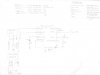
I did a little bit of reverse engineering. There was a component between the mosfet and regulator. It looked like a diode, would that make sense?

I also wasn't sure if R1 was required. I don't see one on Nigels schematics. I'm not sure how to figure out what some of the resistances should be... without the amps and voltage from the pins?

What type of diode and capacitors do I need?


Thanks
 

Attachments

  • tmcc_electronics.jpg
    tmcc_electronics.jpg
    91.9 KB · Views: 520
the diode looks good
I dont see a point to R1 though, linear regulators can draw around 5mA on their own, that would drop 3.4 V on the resistor, leaving only 5.6V at the regulator, unless its LDO that isnt really enough, even then thats neglecting all other current draw...
 
Those 2 leds should be the other way around...

and lose R1, it's only a waste...
 
I don't know what this circuit is supposed to do, or anything about PICs, but shouldn't the PIC have a grd connection (VSS)? What's with that switch to VSS through a resistor? And a 330M resistor in series with the LED? That should probably by 330 ohms? Electrolytic capacitors are generally suitable for linear regulators. I suspect that diode is a reverse diode for the solenoid? Most general purpose diodes will be ok, but faster is better for minimizing the size of the transient spike.

j.
 
where did this circuit come from?
yea that LED resistor should be 330
VSS should be to ground
Both LEDs should be flipped
The input cap on the voltage reg should not be in series
GP3 should probably have a pull up resistor (unless it is using internals)
(reiterating what others said)

Whats the point of this? You say you reverse engineered, but do you have the code for the PIC? It isnt very usefull without it. But looking at the components I doubt it would be very difficult to replicate.

Good luck anyway!
 
Status
Not open for further replies.

Latest threads

New Articles From Microcontroller Tips

Back
Top