Continue to Site

Welcome to our site!

Electro Tech is an online community (with over 170,000 members) who enjoy talking about and building electronic circuits, projects and gadgets. To participate you need to register. Registration is free. Click here to register now.

  • Welcome to our site! Electro Tech is an online community (with over 170,000 members) who enjoy talking about and building electronic circuits, projects and gadgets. To participate you need to register. Registration is free. Click here to register now.

playing with UV LEDs

Status
Not open for further replies.

celery

New Member
Hey folks,

So, in my dumpster rummaging, I found a UV gel nail curing lamp. It has a 24VDC power supply (I metered it at more like 25.3VDC) and powers 30 UV LEDs pretty brightly in strings of 3 LEDs in series with 200 ohm resistors. I have no part numbers or other way to look up their specs, so I did some metering around and found that these LEDs appear to have a Vf of 7.2V, such that with 3 of them in series with a 200 ohm resistor, the resistor only gets about 3.5V across it, yielding a current draw of around 18mA. They are SMD LEDs and luckily I have a heat gun which enabled me to remove a few of them to play around with. I found that I could drive them nicely from a 9V battery using a 100ohm resistor to get around 18mA of current draw.

I did some reading on UV LEDs and learned that they have such high Vf because of the band gap needed to generate these relatively high frequency photons. Given that these things light up quite visibly, they obviously don't emit pure UV (which I assume is true of almost any UV LED), but they definitely get glow-in-the-dark toys to light up and highlighter marking fluoresce nicely under their light. I was wondering if it is possible to calculate their peak frequency based on their Vf of 7.2V. Are there other parameters I need in order to calculate this? Does it basically just come out to power = hν per unit time?

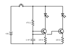
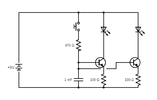
*I'm mostly just curious about the above. In case it's of any interest, I will be using these inside of ping-pong balls that will be the eyes on my niece's spider costume for Halloween. I came up with a stupid circuit that seems to work well with regular white LEDs and 9V battery, but I think I'll have to change some things around if I want to use these UV LEDs. I've attached what I've made on the breadboard. I'm sure it's all wrong, but at least it works. My goal was for my niece to be able to hit a N/O pushbutton sewn into her glove to make the eyes glow and that they would slowly fade out after she releases the button. I seem to have accomplished this with the 1000uF capacitor and the 100ohm emitter resistor. Haven't experimented yet with the UV LEDs. I'd love any suggestions if there's a better way to do this.

Thanks!
Celery
 

Attachments

  • circuit.png
    circuit.png
    6.7 KB · Views: 165
After the button is released, the LEDs appear to be running via the 470 Ohm base resistor. Connecting a diode across that, anode at the cap end, would give higher initial voltage but faster fade.

Be very, very careful with UV LEDs that you do not have data for! The UV output may well be orders of magnitude higher than the visible glow, and if it's short wavelength UV it can cause eye damage if used without protective glasses.

I just found a datasheet for some 400nm UV LEDs, which have a forward voltage around 3.4 - 3.8V at 20mA.
7.2V implies much shorter wavelength - or a different construction..

Edit
And these UV-C types are rated in the 7V range:

Edit 2:
Apparently UV nail lamps are supposed to be UV-A, around the 360 - 400nm range. As long as the original device was properly built the LEDs should not be harmful for indirect exposure, but I'd still be very wary of having them anywhere they are in direct view; ideally they should have a diffuser so the high intensity LED elements are not directly visible.

I've also given myself arc eye a few years ago, from just reflected light from a single high intensity UV LED, that I though I was being careful with!


For info, a lot of high output LEDs, including visible ones, have warnings in the manufacturers data and on the bulk packs that they must not be viewed directly, as the point intensity is incredibly high & far brighter if you focus on it than looking directly at the sun.
UV is far more dangerous as it does not trigger your pupil to contract and protect the retina.

eg. These are just high brightness 5mm visible light LEDs; all colours in that series had the warnings on the packs:

LED_Warning.jpg
 
Last edited:
Wearing glasses with UV block should help protect your eyes.
 
Thank you for these helpful replies! I will say that I can see the internal construction under a magnifying glass and I only see one die (but I don't know for a fact that that means each package isn't more than one junction in series). They are pretty visibly bright and given the original application (cheap nail curing device for home use) I strongly doubt they are UV-C. I never had these LEDs turned on for more than a few seconds at a time, but I absolutely did notice that the light bothered my eyes, even when not in my direct gaze. My thought was that sticking these LEDs inside of ping-pong balls to diffuse their light would probably be fine, and it was definitely not uncomfortable to look at them this way (and they look really cool, fluorescing the ping-pong ball plastic), but I'm assuming ping-pong balls aren't exactly the best UV filters.

rjenkinsgb- those UV-C LEDs you linked to look pretty intimidating. 1700mA current rating...jeez.

I think I'll stick with white LEDs to play it safe. I'll stash these UV LEDs aside for some future project that doesn't involve children trick-or-treating haha.
 
After the button is released, the LEDs appear to be running via the 470 Ohm base resistor. Connecting a diode across that, anode at the cap end, would give higher initial voltage but faster fade.
Are you saying, replace the 470 ohm resistor with a diode going into the base? I will give that a try. Do I not need anything to limit initial current through the capacitor (1000uF electrolytic)?

Edit: I read what you wrote again, no you are not saying that, haha. With the button released, I suppose this would prevent the LED from drawing current from the cap?

Edit #2: What a dope. I just realized I drew my circuit wrong. Or at least, what I drew is not what I have on my breadboard. Here's the corrected diagram. I wanted to saturate the transistor when the button is pressed, and played around with different base resistors, but I never seem to measure a CE voltage less than 3 or 4V. Should I just not use any base resistor and count on the emitter resistor to limit BE current?

Thanks for your help!
 

Attachments

  • circuit (2).png
    circuit (2).png
    6.8 KB · Views: 155
Last edited:
The UV LED's in nail curing lamps are listed as being hazardous to your eyes, so it would make complete sense not to use them for visual purposes. They are also commonly used for curing 3D resin printed parts - we use one at work for doing so.

Interestingly, the lamp we bought for the purpose is Pink :D - simply because Pink was the cheapest colour, and we don't have any concerns about our sexuality :D

Unfortunately nail curing lamps have built-in timers, which are too short for resin curing, but a blob of solder inside soon cured that issue, and it was truly crude inside, as expected from the price. It certainly runs perfectly for considerably longer than it's intended use, but has never failed, and we leave it running in another room.
 
I just realized I drew my circuit wrong.
As you originally drew it, the cap was the only power source with the switch released, which is why I thought a diode may be needed; with the updated drawing, it's fine as it is.

You do need the base resistor as well as the emitter resistors, as without that the base-emitter junction "diode" would pull the emitter to near positive supply and cut the LED off. (Or blow the transistor if the base current was too high).

As it's drawn, it will give a controlled current while the button is pressed & the capacitor charged, then the current will steadily drop off as the cap discharges and the base voltage falls.

It's regulating the current in that mode, by controlling the base (and therefore emitter) voltage, so the current is whatever the emitter resistor sets at that voltage.
OK, thank you for running through that. This is basically what I was thinking when I put this together but I wasn't sure I was reasoning through everything correctly.

I don't yet have all the basics down for using small signal and switching BJTs. Mind if I clarify a few things?

I know I can get Ic by (Vcc-Vbe)/Rb in a common emitter circuit, but here I have an emitter resistor. Can I think of the base-emitter circuit as a diode in the middle of a voltage divider between Rb and Re? (Since the cap charges and looks like an open circuit with the button pressed).

So in this circuit, that would be 100/(470+100) = 0.18, so Ve should be at (8.3V)(0.18)=1.5V, that leaves 8.3V-1.5V=6.8V across Rb (470ohm), giving Ib=14mA.

If saturated, Vce should be like 0.1 or 0.2V tops, and the white LED drops 3.5V (measured), so Re should have 9V-(0.1V+3.5V)=5.4V across it giving (5.4V/100ohm) = 54mA (plus, of course, whatever thr base current is at saturation), which is the emitter current, which should then be the same as the collector current, right?

I'm measuring that Re gets about 4.1V when Rb is 470ohm, and Vce doesn't get less than 1.7V.

But when I use 200ohm for Rb, Vce goes down to 0.2V and Re sees 5.6V, which is closer to what I had calculated for saturation.

Sorry if this is confusing. Mostly I wanted to run my thinking by the gurus here. Does the above look like the scrawlings of a crazy person, or is there some sense in how I'm thinking about this?

Thanks again for your time.
 
Having the emitter resistor changes how the circuit works - it then works like a controlled current source (or current sink). It is controlling the collector current, not voltage, in other words.


The low value base resistor is adding to the emitter current while you have the button pressed, but the principle is still there, as below.

Yours does not have R2 as in the circuit below, but instead the maximum base voltage is set by the current from the 470 Ohm being divided between the two transistors and through their emitter resistors, which limits the maximum capacitor charge voltage.

That current is also part of the emitter resistor current. Once the switch is opened, the current is set almost entirely by the cap voltage and from that the (emitter voltage / emitter resistor value).
With a fractional offset due to the base current, which is collector current / transistor gain.

transistor-active-current-source-01.svg
 
rjenkinsgb- Thank you very much for walking me through that. I feel much more confident in my understanding now, I greatly appreciate your help.

I did go ahead and breadboard out the whole thing to make sure it will work, and it seems to be working fine. I expanded out the circuit to 4 transistor switches, one for each LED. Then I decided to duplicate the circuit, adding another capacitor and pushbutton switch with another four transistors because I decided to install both white and red LEDs inside the pingpong balls. This way my 8 year old niece can be an angry spider if she wants, haha.

One thing that stumped me was that the 1000uF capacitor, discharging through a 100ohm emitter resistor, seemed to give me about the fade time that I wanted. When I built the next LED switch using another small signal NPN BJT with the same pinout, the fade time suddenly took forever. I have no idea what the transistor has to do with this (maybe some of them have higher beta? No idea). I just did the whole thing with 2N2222s and swapped out the 1000uF cap for a 100uF, problem solved ha.

So I wired up the LEDs and hotmelt glued them into my two sizes of ping-pong balls. All that's left to do is solder all the components together, fix these ping-pong balls onto the mask, and make the rest of the spider costume. Thank you again for your help and patience and for educating me!

Here's a video of it on the breadboard:

 
You will not be able you correlate Vf vs wavelength due to design/ process/ power chip size variations.
 
Thanks DrDoggy2,

Yeah I did not use the UV LEDs I had found. I ended up using white and red LEDs that I had had in my bonepile and they work great. I do have some of those 3-legged ones that can be green or yellow/orange, but they are low-power indicators and would have burnt out were I to drive them as brightly as I wanted these to be.
 
Status
Not open for further replies.

Latest threads

New Articles From Microcontroller Tips

Back
Top