Continue to Site

Welcome to our site!

Electro Tech is an online community (with over 170,000 members) who enjoy talking about and building electronic circuits, projects and gadgets. To participate you need to register. Registration is free. Click here to register now.

  • Welcome to our site! Electro Tech is an online community (with over 170,000 members) who enjoy talking about and building electronic circuits, projects and gadgets. To participate you need to register. Registration is free. Click here to register now.

pitch control sensor

Status
Not open for further replies.
Yeah I am really not sure either, just been putting pieces together from other post by the op. Multiple post on same project does make things a bit confusing :)
 
hi again, and thankx for ur responds guys. and about the questions u asked:
no i'm not from the middle east even though that they r very good people , but i'm from libya and it's in north africa, and my project's only mission is to apply what i've learned in my past semsters, so i can have the high deploma in a peaceful way.:)
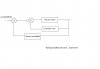
about the ultrasonic sensor ,no i'm not going to use it for controlling the airplane from the base.
coz i'm going to control the airplane movements by an RF transmitter "27MHz" which is going to be connected to the PC via an LPT..
if u r wondering about the function of the ultrasonic sensor! it's going to be making sure that the airplane altitude won't axceed 4 meters, and the reason why i chose the altitude rang that way, is bcoz i have an altrasonic sensor in that specific distance range!
so if i send "up command" to the airplane, first it will have to check that it's not flying in the 4 m range, if so it will not take the command ..
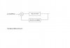
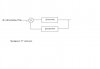
so the adjustments of the airplane movement will take place in the receiver part, if u want to see the circuit block diagram, it is as the following:
 

Attachments

  • altitude control.JPG
    altitude control.JPG
    15.4 KB · Views: 207
Last edited:
Ok, my bad. Sorry I misunderstood. Seems like you put some thought into this. Now that we have a better picture we might be able to give better answers. Did you get your PC to remote interface working based on Erics suggestions?
Shoot, I shoulda remembered the RC remote, some reason I started thinking usonic link. duh...
Maybe if you keep all project questions in one link so us memory impaired guys can keep things straight :)
 
OK, looks like you have the easy part (alt) sorted. How do you plan on using the system. Completely autonomous flight, assisted flight (ie: the sensors in the plane must limit the turn radius and pitch angle to a set safety limit?).
I still don't think you will get anything usable from just the acellerometer alone. If you have a plane with very high dihedral you might get away with only using a gyro on the ussumption that the plane is level if no rudder/ail input is sent to the plane.
 
Last edited:
OK, looks like you have the easy part (alt) sorted. How do you plan on using the system. Completely autonomous flight, assisted flight (ie: the sensors in the plane must limit the turn radius and pitch angle to a set safety limit?).
I still don't think you will get anything usable from just the acellerometer alone. If you have a plane with very high dihedral you might get away with only using a gyro on the ussumption that the plane is level if no rudder/ail input is sent to the plane.

Wow, your going a few meters over my head. So if I understand your concerns, your talking about keeping the plane level. Could the gyro or whatever gizmo used provide feedback to the PC and the PC make corrections back to the craft? This stuff is new to me so I dunno squat. Just curious. :eek:
 
Yes, that is the short of it. Most DIY autopilots use a gyro/accelerometer combo with Kalman filter. I only know PIC's, which is not really powerfull enough to run a decent kalman filter routine so I opted for the thermopiles to "look at the horizon".
The thermopiles are used on the basis that the earth is always warmer than the sky (even with snow on the ground), so with left and right pointing thermopiles you can see that the plane is tilted when you see more heat on one side and less on the other.
 
No kidding, thermopiles huh. I will have to look that up. Sounds clever.
 
Have a look here: **broken link removed**

Thanks for the link. As soon as I saw the photo, I said to myself, so thats what those things were... I had a few devices that looked just like that but I could not figure out what they were for. I will have to check my junkbox for them.
 
i got ur idea boomslang, and yes that was what i'm going to do if i found a gyroscope , i'll use both "if the God will" gyro and accelerometer IC where every sensor will have it's own circuit like the pics display ,but right now i'm trying the altitude control circuit and if it worked i'll do the rest.
but if i don't have much time i guess i'll control the yaw of the airplane by the rate..
anyway thanx for ur reply, u and mike.
 

Attachments

  • altitude & pitch  control.JPG
    altitude & pitch control.JPG
    19.2 KB · Views: 195
  • yaw control.JPG
    yaw control.JPG
    14.9 KB · Views: 162
ok i'll keep that in my mind thanx for every thing , and wigh u the best of luck, c u :)
 
hey guys, i wanna ask u somehing that i heared early this evening.
it's about using the compass as a yaw rate sensor!!!
so is there anyone knows about this thing???
thanx in advance
 
A compass (magnetometer) will not work while the plane is tilted. You do get tilt compensating units, but even these don't work 100% on the airplanes.

btw: The compass will only give heading, you need to take 2 heading readings at a certain interval... do some maths and it will give you yaw rate.
 
hello everyone, can u plz look at the pic attatched and tell me if what i stated is right or wrong ??
if it's right:
let's suppose that we have a 10 cm fuselage ok, and that the airplane is flying with an attitude of let's say 2m and we send a pitch down command for the airplane, and we want it to produce 30 degree angle of pitch , so depending on the rule whitch says that if we want 30 degree angle of a triangle then the fronting line of the wanted angle must be equal to the half of the rad line so using that would produce the following:
as the rad is equal to the half of the fuselage length then rad =5cm, ok!
and the half of the rad will be equal to 2.5cm right?
so the fronting line must be 2.5cm to get 30 degree pitch angle
and as i supposed above that the attitude is 2m=200cm
then to provide the wanted angle, that attitue must be decreamented by 2.5cm...
so is that right or i'm in the wrong way???
thanx in advance
 

Attachments

  • pitch angle.JPG
    pitch angle.JPG
    30.7 KB · Views: 160
Status
Not open for further replies.

Latest threads

New Articles From Microcontroller Tips

Back
Top