Continue to Site

Welcome to our site!

Electro Tech is an online community (with over 170,000 members) who enjoy talking about and building electronic circuits, projects and gadgets. To participate you need to register. Registration is free. Click here to register now.

  • Welcome to our site! Electro Tech is an online community (with over 170,000 members) who enjoy talking about and building electronic circuits, projects and gadgets. To participate you need to register. Registration is free. Click here to register now.

PIR sensor, help!

Status
Not open for further replies.

TheSwede73

New Member
Hey!

I have just recieved two PIR sensors, (passiveinfraredsensors) and im trying to put it into a circuit.
The final project is two get a outdoorlight to turn on and light for 10 minutes, thats done with a timer, that part i can figure out!

What i need to know is how to connect this correctly.

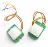
The markings are red - "plus", black - "minus", yellow -"out", so three cables.

How do i connect it to get the signal to close a timer relay?

and can i test it before that, just turning on a led or something.

The Pirs come with circuitry ready as in picture.

Thanks!!
 

Attachments

  • screen-capture-8.png
    screen-capture-8.png
    221.6 KB · Views: 593
Need a part number or data sheet for the PIR. Otherwise it's only a guess as to what voltages it needs/outputs.
 
Throw the unknown product back to the seller and buy one from a half-decent seller who can give you the manufacturer's datasheet for one.
 
The same product can be bought from other stores so i think i can get the sheet... but how hard can it be? i have plus, minus, and out.. so i only need to get a signal to close a relay...shouldnt be hard...
 
Could "out" be an open collector? and i need a pull up resistor? out is the "alarm" pin? i have read this on the same looking PIR's somewhere else...
i dont know half of it :) but if this works with my PIR's...
 
Without seeing the datasheet then you are just guessing on its spec's and how it works.
 
Yes! :)
Well i paid 7 dollars for both..so i can experiment...

But what's this..you are an incredible expert, no advice?

Please
 
i tend to agree with you that it is most likely an open collector output.

it should be easy enough to figure out. supply the sensor with power and use your volt meter with light and dark and see what the output does. if the output doesnt move much with the light and dark scenarios it is probably an open collector. at this point use a pull up resistor and scope it again...
 
But what's this..you are an incredible expert, no advice?

Please

He gave you his advise, twice....

audioguru said:
Throw the unknown product back to the seller and buy one from a half-decent seller who can give you the manufacturer's datasheet for one.

audioguru said:
Without seeing the datasheet then you are just guessing on its spec's and how it works.
 
Try this. Connect the Red to +from supply,Black to the -of supply,Yellow to the relay coil one side,and the other side of coil to -of supply.Basically the Pir needs a power source to run its detection, and when activated, sends a switched power out to the relay/appliance.
 
My best guess is that it's open drain (collector). This would mean that a relay would work between red (+) and the yellow wire. Probably a good idea to use a diode (1N914, 1N4148, etc) across the relay coil. The cathode goes to the (+) or red.

It's anybody's guess whether it's normally open or normally closed. Normally open is most convenient for connecting light controls in parallel, while normally closed helps to make alarm systems tamper resistant.

View attachment k133.pdf
You're right.Found this maybe some help.Could be similar.
 
It is odd that the datasheet for the PIR sensor shows a 10k load but does not spec a max allowed output current.

Its output might not be able to drive a relay. Maybe you need to "smoke" one to see if it will or won't drive a relay.
 
I can order relays that close by the out of as little as a LED, so that would probably work...

Well for 3,50 each i guess i could test one to the max....
 
I can order relays that close by the out of as little as a LED, so that would probably work...

Well for 3,50 each i guess i could test one to the max....

Dont forget to put a diode across the relay coil.:)
 
Why?= :)

So that no current cant go the other way? but the relaycircuit is already made, its a board..plug and play.

The back emf from the relay coil when it de-energises creates a high voltage which could take out the transistor.

Use a 1N4148 or 1N4004..diode cathode to the +V supply and the anode to the output. OK.?:)
 
Last edited:
A diode is necessary. If one is already included on the relay board, that's good. You don't need two.
 
Status
Not open for further replies.

Latest threads

New Articles From Microcontroller Tips

Back
Top