Continue to Site

Welcome to our site!

Electro Tech is an online community (with over 170,000 members) who enjoy talking about and building electronic circuits, projects and gadgets. To participate you need to register. Registration is free. Click here to register now.

  • Welcome to our site! Electro Tech is an online community (with over 170,000 members) who enjoy talking about and building electronic circuits, projects and gadgets. To participate you need to register. Registration is free. Click here to register now.

PIN photodiode light detector circuit looks wrong.

Status
Not open for further replies.

Flyback

Well-Known Member

Attachments

  • Light detector schematic _1.pdf
    9.3 KB · Views: 126
Last edited:
Hi FB,

The LVM321 does not list the nominal worst-case common-mode input voltage range for 3.3V supply lines but, extrapolating between the data for 5v supply lines and 2.7V supply lines, gives the following figures:
Supply line__input low__input high
2.7V________0V______1.7V
5v__________0V______4V
3.3V_________0V_____2.3V

So, from what you say, yes the common mode voltage range is exceeded.

Also, bear in mind that the actual common-mode range will be affected, in some cases adversely, by temperature, loading, etc and the supply-line voltage actually on the pins of the opamp.

A rail to rail input, output (RRIO) opamp would be a better choice. And an over the rails opamp would be an even better choice.

spec
 
Thanks, i remember years ago having an opamp with input above the common mode input range, and its output just latched up high and stayed high.....even when the input fell back inside the common mode input range of the opamp.
As such, do you agree that any operation whatsoever, with an input outside the common mode input range is totally unacceptable?
By the way , do you agree that the photodiode is an extremely high value resistor when no light is incident on it, but is a 0.4v Vf diode when light shines on it?
 
The circuit for U1 does not violate the op amp's common-mode range. The one on the right for U2 does, though: from the op amp data sheet, looking at the specs for both 2.7V and 5.0V operation, it appears the common-mode range does not extend closer to the positive supply than 1 volt; so U2's 2.7V input bias level is clearly outside the allowable input range.
 
As such, do you agree that any operation whatsoever, with an input outside the common mode input range is totally unacceptable?
That's my policy.

By the way , do you agree that the photodiode is an extremely high value resistor when no light is incident on it, but is a 0.4v Vf diode when light shines on it?
A photodiode acts like a light-controlled current source; it doesn't behave like a resistor or a forward-biased diode.
 
Thanks, it looks to me that the Left hand opamp is "supposed" to see its output go high when light is incident on the photodiode there.
..and it looks like the Right hand circuit is "supposed" to see its output go low when light is incident on its photodiode. Would you agree?

Another problem to me is that each circuit probably acts just like a follower (opamp buffer) when no light is incident on its respective photodiode...and this would make the respective output be 0.6V and 2.7V respectively...and these are a little too near the microcontroller's high/low threshold of 2.2v/0.8v. (the opamps feed into a 3v3 microcontroller)
 
Thanks, i remember years ago having an opamp with input above the common mode input range, and its output just latched up high and stayed high.....even when the input fell back inside the common mode input range of the opamp.
Yes, that was one of the big problems with early opamps which could even destroy the whole chip when they latched up.

The problem was mainly caused by a phase inversion, so that in a negative feedback amplifier the feedback would become positive and hence the opamp would latch, like a Shmitt trigger.

But practically all later opamps fixed this problem and it is now rare to get latch-up, expect is very high frequency amplifiers
As such, do you agree that any operation whatsoever, with an input outside the common mode input range is totally unacceptable?
It is a bit more complicated than that.

What we have been discussing is the input common-mode range where the opamp will meet its data sheet specification: open loop gain, frequency response, etc

But there is also a safe common mode input voltage range and a safe differential mode input voltage range. With most modern opamps you can take the inputs to 200mV above the positive supply line and 200mV below the negative supply line without damage.
By the way , do you agree that the photodiode is an extremely high value resistor when no light is incident on it, but is a 0.4v Vf diode when light shines on it?
Photo diodes tend to have a high impedance even when subject to photons. The photons cause the diode to produce a current that comes from a high impedance. But it varies with the diode concerned and what is actually integrated with the diode.

spec
 
By the way FB, you can make pretty much any opamp into an amplifier with a linear input voltage range way above and below the supply lines by going for an inverting, virtual earth amplifier.

spec
 
In the circuit of post #1, which has only just shown on my PC, the photodiodes doe not appear to to have a high enough voltage bias (0.6V and 2.7V).

spec
 
Thanks, it looks to me that the Left hand opamp is "supposed" to see its output go high when light is incident on the photodiode there.
..and it looks like the Right hand circuit is "supposed" to see its output go low when light is incident on its photodiode. Would you agree?
Yup.

Another problem to me is that each circuit probably acts just like a follower (opamp buffer) when no light is incident on its respective photodiode...and this would make the respective output be 0.6V and 2.7V respectively...and these are a little too near the microcontroller's high/low threshold of 2.2v/0.8v. (the opamps feed into a 3v3 microcontroller)
The circuits' outputs are feeding into microcontroller digital inputs??? Not good.
 
Both opamps are current to voltage converters. They turn the current from the photodiode into a voltage.

The transfer function for both opamps is Vout = Ioptodiode * 27K.

This is a standard approach to read the small current from an photodiode and at the same time maintain a constant voltage across the photodiode.

Because of the virtual earth function of the opamp the circuit is also fast and low distortion.

spec
 
The transfer function for both opamps is Vout = Ioptodiode * 27K.
Thanks, so the left hand opamp has its output at 0.6V when its photodiode s in darkness, and then its output progressively creeps up toward 3v3 as more and more light shines on its photodiode?
…and the right hand opamp starts with its output at 2v7 when in darkness, and its output creeps progressively downward from that as more and more light is shined on its photodiode?

But we still agree that the right hand opamp circuit is likely to be bogus because it has an input above its input common mode range?

In fact the left hand opamp circuit will also likely go bogus when strong light is shined on its photodiode , because then it will have an input above its common mode input range?

The circuits' outputs are feeding into microcontroller digital inputs??? Not good.
errr, sorry , they may actually be going into an ADC..in fact probably are
 
Thanks, so the left hand opamp has its output at 0.6V when its photodiode s in darkness, and then its output progressively creeps up toward 3v3 as more and more light shines on its photodiode?
That is correct
…and the right hand opamp starts with its output at 2v7 when in darkness, and its output creeps progressively downward from that as more and more light is shined on its photodiode?
That is also correct
But we still agree that the right hand opamp circuit is likely to be bogus because it has an input above its input common mode range?
Yes
In fact the left hand opamp circuit will also likely go bogus when strong light is shined on its photodiode , because then it will have an input above its common mode input range?
No that is not correct. The left hand opamp inputs will always be at 0.6V. The output from the opamps can swing rail to rail
errr, sorry , they may actually be going into an ADC..in fact probably are
It is not known what the opamp output connects to. But as long as it is a relatively high input impedance, which is likely, it makes no difference what it is, even an ADC.

spec
 
yes i agree, i think OBW and i were worried that the micro wouldnt make much sense of the input if it was into a digital input, as opposed to an ADC.
Thanks for your great replies, and you have cracked it, as it makes total sense as i believe it is a light sensor, though i wonder what the part to part tolerance is on the current of the photodiode, ..because perhaps different batches of photodiode will give well different readings for the same light level in this circuit.
Yes, you are wise to consider the whole circuit so that you have all corners covered.:)

spec
 
thanks, i actually think the circuit is bogus...the tolerance on the optodiode current per light unit is likely to be widely different from batch to batch of photodiodes.
 
thanks, i actually think the circuit is bogus...the tolerance on the optodiode current per light unit is likely to be widely different from batch to batch of photodiodes.

Yes, but it all depends what the intended circuit function is.

Also, the photodiodes could be precision calibrated types.

It is possible that a microprocessor could be used to calibrate the system and compensate for any non-linearities.

spec
 
Thanks, i remember years ago having an opamp with input above the common mode input range, and its output just latched up high and stayed high.....even when the input fell back inside the common mode input range of the opamp.
As such, do you agree that any operation whatsoever, with an input outside the common mode input range is totally unacceptable?
By the way , do you agree that the photodiode is an extremely high value resistor when no light is incident on it, but is a 0.4v Vf diode when light shines on it?

Hi,

I have two types but unfortunately i dont think i have the part numbers for either type.

The first type is high speed, and will put out about 0.6v or so when light shines on it, but can also be used in series mode where little current is passed until light hits it. This might be able to be classified as a photo voltaic 'diode' of which all silicone diodes are to some extent, but it was sold as a pin photo diode. Diode unit price can range from maybe 50 cents to over 100 dollars (USD) and signals range up to 10GHz.

The second type will not put out any voltage at all. It will just turn into a lower value resistor when light is directed at it. This means that if you put it in series with a voltage source it will allow current to flow when light is directed on it.
For example in the circuit:
+5v o---10k---+---|>|---o Ground

you will see +5v at the anode to ground (across the diode) until you shine light on the diode and then it will go down to a lower level where the level of voltage then depends on the intensity of light.


For the first type above (photovoltaic type) for this circuit:
Meter o---|>|---o Ground

there is no resistor, no voltage source, but when you shine light on the diode the meter reads maybe 0.6v or so.
Alternately to keep noise down, you could place a 5k resistor across that diode above and then read the voltage with a scope and when you direct an IR remote control at the diode you'll see the protocol pulses. You can also see the carrier if you set the scope right and back the IR remote away from the diode a little while pressing a button.
You can not use the non photovoltaic type like this, but you could also use this first type with a series resistor as before while looking across the resistor instead of the diode.

The difference between types could be due to the intrinsic layer thickness, but i never looked into this.

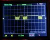
Here is a scope pic of the second type with 10k in series, and using a low voltage power source just above 2vdc. The scope is looking across the diode, and the pulses are from a typical IR remote control. The protocol pattern is seen as the burst pulses, and the carrier is shown as the higher frequency component in each pulse although it alternates faster than the scope presents on that time base setting. The protocol pattern is inverted because the scope is across the diode not the resistor.
This does show that the series resistance of the diode must be much lower than 10k.
 

Attachments

  • MiniScope-01.jpg
    MiniScope-01.jpg
    91.6 KB · Views: 107
Last edited:
Status
Not open for further replies.

Latest threads

New Articles From Microcontroller Tips

Back
Top