Continue to Site

Welcome to our site!

Electro Tech is an online community (with over 170,000 members) who enjoy talking about and building electronic circuits, projects and gadgets. To participate you need to register. Registration is free. Click here to register now.

  • Welcome to our site! Electro Tech is an online community (with over 170,000 members) who enjoy talking about and building electronic circuits, projects and gadgets. To participate you need to register. Registration is free. Click here to register now.

PIC16F887 RB0 INTERRUPT

Status
Not open for further replies.

Kylobeetle

Member
Hello again guys, its me again :p .. this time im playing (or trying to) with RB0 external interrupt, since i finally could control the UART interrupts now im trying to understand the external interrupt. For this dutty i have made some research (also i tried to look here but no luck) and I found a "working" code, i ran it and the code works, but the interrupt doesnt. So i have read the datasheet multiple times and i have understood that important values like, rising edge, global interrupt, rb0 interrupt, who is output and input are correct but i cant understand why is not working... I ll post this borrowed code just for learning purposes since my code are packed in headers and this one is fastest for posting purposes haha.

Code:
#define _XTAL_FREQ 4000000
#define RS RD2
#define EN RD3
#define D4 RD4
#define D5 RD5
#define D6 RD6
#define D7 RD7

#include <xc.h> 
#include "config.h"
//LCD Functions Developed by Circuit Digest.
void Lcd_SetBit(char data_bit) //Based on the Hex value Set the Bits of the Data Lines
{
if(data_bit& 1) 
D4 = 1;
else
D4 = 0;

if(data_bit& 2)
D5 = 1;
else
D5 = 0;

if(data_bit& 4)
D6 = 1;
else
D6 = 0;

if(data_bit& 8) 
D7 = 1;
else
D7 = 0;
}

void Lcd_Cmd(char a)
{
RS = 0;           
Lcd_SetBit(a); //Incoming Hex value
EN  = 1;         
        __delay_ms(4);
        EN  = 0;         
}

void Lcd_Clear()
{
Lcd_Cmd(0); //Clear the LCD
Lcd_Cmd(1); //Move the curser to first position
}

void Lcd_Set_Cursor(char a, char b)
{
char temp,z,y;
if(a== 1)
{
 temp = 0x80 + b - 1; //80H is used to move the curser
z = temp>>4; //Lower 8-bits
y = temp & 0x0F; //Upper 8-bits
Lcd_Cmd(z); //Set Row
Lcd_Cmd(y); //Set Column
}
else if(a== 2)
{
temp = 0xC0 + b - 1;
z = temp>>4; //Lower 8-bits
y = temp & 0x0F; //Upper 8-bits
Lcd_Cmd(z); //Set Row
Lcd_Cmd(y); //Set Column
}
}

void Lcd_Start()
{
  Lcd_SetBit(0x00);
  for(int i=1065244; i<=0; i--)  NOP(); 
  Lcd_Cmd(0x03);
__delay_ms(5);
  Lcd_Cmd(0x03);
__delay_ms(11);
  Lcd_Cmd(0x03); 
  Lcd_Cmd(0x02); //02H is used for Return home -> Clears the RAM and initializes the LCD
  Lcd_Cmd(0x02); //02H is used for Return home -> Clears the RAM and initializes the LCD
  Lcd_Cmd(0x08); //Select Row 1
  Lcd_Cmd(0x00); //Clear Row 1 Display
  Lcd_Cmd(0x0C); //Select Row 2
  Lcd_Cmd(0x00); //Clear Row 2 Display
  Lcd_Cmd(0x06);
}

void Lcd_Print_Char(char data)  //Send 8-bits through 4-bit mode
{
   char Lower_Nibble,Upper_Nibble;
   Lower_Nibble = data&0x0F;
   Upper_Nibble = data&0xF0;
   RS = 1;             // => RS = 1
   Lcd_SetBit(Upper_Nibble>>4);             //Send upper half by shifting by 4
   EN = 1;
   for(int i=2130483; i<=0; i--)  NOP(); 
   EN = 0;
   Lcd_SetBit(Lower_Nibble); //Send Lower half
   EN = 1;
   for(int i=2130483; i<=0; i--)  NOP();
   EN = 0;
}

void Lcd_Print_String(char *a)
{
int i;
for(i=0;a[i]!='\0';i++)
  Lcd_Print_Char(a[i]);  //Split the string using pointers and call the Char function 
}
/*****End of LCD Functions*****/


/****Interrupt function ****/
void interrupt ISR_example()
{
        if (INTF==1) //External Interrupt detected
        { 
            Lcd_Clear();
            Lcd_Set_Cursor(1,1);
            Lcd_Print_String("  Entered ISR");
           INTF = 0;          // clear the interrupt flag after done with it
           __delay_ms(2000);
            Lcd_Clear();
        }
}
/****End of Interrupt Function****/

int number =0;
char ch1,ch2,ch3,ch4;
int main()
{
    TRISD = 0x00; //PORTD declared as output for interfacing LCD
    TRISB0 = 1;        //DEfine the RB0 pin as input to use as interrupt pin
    OPTION_REG = 0b00000000;  // Enables PULL UPs
    GIE=1;          //Enable Global Interrupt
    PEIE=1;         //Enable the Peripheral Interrupt
    INTF=0;
    INTE = 1;       //Enable RB0 as external Interrupt pin
    Lcd_Start();
   
    while(1)
    {
        ch1 = (number/1000)%10;
        ch2 = (number/100)%10;
        ch3 = (number/10)%10;
        ch4 = (number/1)%10;
       
        Lcd_Set_Cursor(2,1);
        Lcd_Print_String("Inside Main Loop");
        Lcd_Set_Cursor(1,1);
        Lcd_Print_String("Number: ");
        Lcd_Print_Char(ch1+'0');
        Lcd_Print_Char(ch2+'0');
        Lcd_Print_Char(ch3+'0');
        Lcd_Print_Char(ch4+'0');
       
        __delay_ms(500);
        number++;
       
    }
    return 0;
}

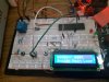
In this code you will find the Init for the 16X2 LCD also a counter, which will represent the main program, the idea would be press RB0 and show that you are in an ISR then return back to the count.. i dont know if my problem is during my electrical conections which im almost sure that are not.. (i ll still check it again if is needed) .. thanks beforehand.
 
First make sure your code is running - is the oscillator set right - is the WDT disabled - is it getting through the initialisation code. The delay in your LCD init could take 2 weeks if the clock is running at 32kHz!

The easiest way to do this is by blinking an LED in your main code.

Mike.
 
I have checked the code before posting it here. and of course i have tested it. I have upload a photo showing it. by default this pic (16F887) will run at 4mhz .. thats what the datasheet says. and thats how i have always worked with it.

here i ll share my configuration bits file to show its content, this is the file i always use to compile my codes, i only declade internal use of the clock the other features are off since im not using them

Code:
// PIC16F887 Configuration Bit Settings

// 'C' source line config statements

// CONFIG1
#pragma config FOSC = INTRC_NOCLKOUT// Oscillator Selection bits (INTOSCIO oscillator: I/O function on RA6/OSC2/CLKOUT pin, I/O function on RA7/OSC1/CLKIN)
#pragma config WDTE = OFF       // Watchdog Timer Enable bit (WDT disabled and can be enabled by SWDTEN bit of the WDTCON register)
#pragma config PWRTE = OFF      // Power-up Timer Enable bit (PWRT disabled)
#pragma config MCLRE = OFF      // RE3/MCLR pin function select bit (RE3/MCLR pin function is digital input, MCLR internally tied to VDD)
#pragma config CP = OFF         // Code Protection bit (Program memory code protection is disabled)
#pragma config CPD = OFF        // Data Code Protection bit (Data memory code protection is disabled)
#pragma config BOREN = OFF       // Brown Out Reset Selection bits (BOR enabled)
#pragma config IESO = OFF       // Internal External Switchover bit (Internal/External Switchover mode is disabled)
#pragma config FCMEN = OFF      // Fail-Safe Clock Monitor Enabled bit (Fail-Safe Clock Monitor is disabled)
#pragma config LVP = OFF        // Low Voltage Programming Enable bit (RB3 pin has digital I/O, HV on MCLR must be used for programming)

// CONFIG2
#pragma config BOR4V = BOR40V   // Brown-out Reset Selection bit (Brown-out Reset set to 4.0V)
#pragma config WRT = OFF        // Flash Program Memory Self Write Enable bits (Write protection off)

// #pragma config statements should precede project file includes.
// Use project enums instead of #define for ON and OFF.


while im typing this, the counter still running of this program, the only thing is not working, its the ISR routine, (external interrupt) i have to press a push bottton and a message saying (ISR) should appear in my LCD leting me know that the ISR is working but is not. i have took a read over this code and compared it witht he data sheet to see if it has its flags in the propper state but so far seems they are alright. also.. i have tried use a led to make this interrupt! in fact, i tried to use my own code!! haha but i felt kinda desmotivated because it didnt work as i expected, because of that i wanted to see somelse code working to confirm that my problem was in my code, but even this working code is failing at the ISR. so i dont know if something electrical in my breadboard or im missing something,
 

Attachments

  • WhatsApp Image 2018-05-14 at 10.28.33 PM.jpeg
    WhatsApp Image 2018-05-14 at 10.28.33 PM.jpeg
    116.9 KB · Views: 187
As you've been told many times. Do not put delays and calls to LCD routines in an interrupt. Set a flag and test it in your main code. Oh, wait, your main code has a return 0; in it - where do you think it is going to return too?

It's probably running your initialisation code over and over again.

Mike.
 
Hello mike, good morning from Panama, I ll hear your advice, and I will compile a short code only using leds and lets work over that, in the other hand, whats wrong with this return 0 ? i mean isnt the same as void ? in the end, we dont want a value from this function (main) since arent we paying attention to their outputs ? .. not sure if i will be able to test my own code today, today and tomorrow may be very busy days at work but right now i have some spare time to compile in notepad++ the code i think it may work. but i have my doubts .. here i Go.
 
In DOS or windows you can return from main and it will return to the operating system. In a micro controller it has nowhere to return to so it crashes. Always stay in an infinite loop in your main code.

Mike.
 
Port B inputs default to analog. I don't see where you are clearing the analog function.

You are doing a LOT of things in the interrupt routine. As Pommie mentioned, set a flag and handle the LCD stuff in the main loop.

I don't remember where I saw this (or even if it's a thing) but I always enable GIE as the last step after enabling all the interrupt sources. For example:

Code:
    GIE=0;          //Disable Global Interrupt to make changes
    PEIE=1;         //Enable the Peripheral Interrupt
    INTF=0;
    INTE = 1;       //Enable RB0 as external Interrupt pin
    GIE=1;          //Enable Global Interrupt

You are changing the entire OPTION_REG from the reset values (0b11111111). There's probably nothing other than the pull-up and interrupt edge that would cause you an issue but you may want to double-check.
 
Hello again guys, lets work on this simply piece of code, where we can focus on the main concept of the ISR and not other factors like the LCD.

Code:
#include <xc.h>

// PIC16F887 Configuration Bit Settings

// 'C' source line config statements

// CONFIG1
#pragma config FOSC = INTRC_NOCLKOUT// Oscillator Selection bits (INTOSCIO oscillator: I/O function on RA6/OSC2/CLKOUT pin, I/O function on RA7/OSC1/CLKIN)
#pragma config WDTE = OFF       // Watchdog Timer Enable bit (WDT disabled and can be enabled by SWDTEN bit of the WDTCON register)
#pragma config PWRTE = OFF      // Power-up Timer Enable bit (PWRT disabled)
#pragma config MCLRE = OFF      // RE3/MCLR pin function select bit (RE3/MCLR pin function is digital input, MCLR internally tied to VDD)
#pragma config CP = OFF         // Code Protection bit (Program memory code protection is disabled)
#pragma config CPD = OFF        // Data Code Protection bit (Data memory code protection is disabled)
#pragma config BOREN = OFF       // Brown Out Reset Selection bits (BOR enabled)
#pragma config IESO = OFF       // Internal External Switchover bit (Internal/External Switchover mode is disabled)
#pragma config FCMEN = OFF      // Fail-Safe Clock Monitor Enabled bit (Fail-Safe Clock Monitor is disabled)
#pragma config LVP = OFF        // Low Voltage Programming Enable bit (RB3 pin has digital I/O, HV on MCLR must be used for programming)

// CONFIG2
#pragma config BOR4V = BOR40V   // Brown-out Reset Selection bit (Brown-out Reset set to 4.0V)
#pragma config WRT = OFF        // Flash Program Memory Self Write Enable bits (Write protection off)

// #pragma config statements should precede project file includes.
// Use project enums instead of #define for ON and OFF.


void interrupt ISR() {

    if(INTF == 1) {  //check for interrupt flag
        INTF = 0;    //Clear the interrupt
        if(RB1 == 1) { //If the LED is on
            //turn off the LED
            RB1 = 0;
        }
        else {  //If the LED is off
            RB1 = 1;  //turn on the LED
        }
    }
}


void main() {
   
    TRISB0 = 1;   //RB0 as a input
    TRISB1 = 0;    //RB1 as a output
    RB1 = 1;  //RB1 high so LED On
    GIE = 1;   //Enable the Global interrupt
    PEIE =1;  //Peripheral Interrupt Enable
    INTE = 1;      //enable RB0 interrupt
  // Do I do need to use OPTION_REG to set rising or falling edge ? or is not mandatory.
    while(1); // perm loop
   
}

I have my doubts about the OPTION_REG , also i would be using external resistor for the push botton. how this code looks ? i cant compile right now, im just trying to handle the idea. if im missing something let me know to explain or add.

Kylo
 
Port B inputs default to analog. I don't see where you are clearing the analog function.

RB0 shares functions with analog input AN12. Analog input is the power-on/reset default for RB0. You need to disable the analog input (to make it a digital input) with the ANSELH register. Read section 3.4.1 of the datasheet, DS40001291H
Alright buddy, i ll try this if the day let me today.. this only make me wonder, when i started to play with this MCU, i always used b ports, and turned on leds but never used that option to enable digital output, why is now causing me troubles ?
 
Read section 3.4.1 of the datasheet.

"The ANSELH register (Register 3-4) is used to configure the input mode of an I/O pin to analog"

"The state of the ANSELH bits has no affect on digital output functions"
 
PORTB being analogue is not a problem if you're never reading it as it will always read zero when analogue.

In your code you read portb in the ISR,
Code:
        if(RB1 == 1) { //If the LED is on
            //turn off the LED
            RB1 = 0;
        }
        else {  //If the LED is off
            RB1 = 1;  //turn on the LED
        }
The if(RB1==1) will always read zero so will not change the LED state.

Here is your code with the corrections,
Code:
#include <xc.h>
// PIC16F887 Configuration Bit Settings

// CONFIG1
#pragma config FOSC = INTRC_NOCLKOUT// Oscillator Selection bits (INTOSCIO oscillator: I/O function on RA6/OSC2/CLKOUT pin, I/O function on RA7/OSC1/CLKIN)
#pragma config WDTE = OFF       // Watchdog Timer Enable bit (WDT disabled and can be enabled by SWDTEN bit of the WDTCON register)
#pragma config PWRTE = OFF      // Power-up Timer Enable bit (PWRT disabled)
#pragma config MCLRE = OFF      // RE3/MCLR pin function select bit (RE3/MCLR pin function is digital input, MCLR internally tied to VDD)
#pragma config CP = OFF         // Code Protection bit (Program memory code protection is disabled)
#pragma config CPD = OFF        // Data Code Protection bit (Data memory code protection is disabled)
#pragma config BOREN = OFF       // Brown Out Reset Selection bits (BOR enabled)
#pragma config IESO = OFF       // Internal External Switchover bit (Internal/External Switchover mode is disabled)
#pragma config FCMEN = OFF      // Fail-Safe Clock Monitor Enabled bit (Fail-Safe Clock Monitor is disabled)
#pragma config LVP = OFF        // Low Voltage Programming Enable bit (RB3 pin has digital I/O, HV on MCLR must be used for programming)

// CONFIG2
#pragma config BOR4V = BOR40V   // Brown-out Reset Selection bit (Brown-out Reset set to 4.0V)
#pragma config WRT = OFF        // Flash Program Memory Self Write Enable bits (Write protection off)

void interrupt ISR() {
    if(INTF==1 && INTE==1) {  //check for interrupt flag
        INTF = 0;    //Clear the interrupt
        if(RB1 == 1) { //If the LED is on
            //turn off the LED
            RB1 = 0;
        }
        else {  //If the LED is off
            RB1 = 1;  //turn on the LED
        }
    }
}

void main(){
    TRISB0 = 1;   //RB0 as a input
    TRISB1 = 0;    //RB1 as a output
    ANSEL=0;
    ANSELH=0;
    RB1 = 1;  //RB1 high so LED On
    GIE = 1;   //Enable the Global interrupt
    PEIE =1;  //Peripheral Interrupt Enable
    INTE = 1;      //enable RB0 interrupt
    OPTION_REGbits.nRBPU=0;     //turn on portB pullups
    while(1); // perm loop
}

Mike.
 
Last edited:
Damn... Mike, you are very deep into this, I considered today that i need a good book for my good understanding of this topic, do you know a good book for me that i could buy or something? today i found some but if you know something that you could considerer better would be awesome, something like, C embedded for starters, or anything like that haha now lets see why your code works and mine doesnt. i want to understand what i was doing wrong. i noticed that you said this

PORTB being analogue is not a problem if you're never reading it as it will always read zero when analogue.

yet i saw that you added
Code:
ANSEL=0;
    ANSELH=0;

was that necesary ? despite of what you said back then ? . Im here reading and understanding.
 
Alright, i wanted to update this .. I made some changes and Disabled the
Code:
ANSEL=0;
    ANSELH=0;
and the code didnt work any more (i mean, stuck with no ISR)
also i removed temporally this && INTE==1

and i got the 1st result i spected, the led would rotate between on and off, depending on its last state. i was trying to figure out the reason of comparing that flag, if i have already declared it in my main routine.

for what im understanding is, its about the analog/digital features, it gave me problems before when i was playing with the LCD, I only could use it in C and D ports, but not A or B. then i got told about the analog stuff..
 
I've no idea what you have done. Did you remove the ANSEL lines?

The above code should work as it is. It will not work without the ANSEL lines.

The reason for if(INTF==1 && INTE==1) is to make sure the interrupt is enabled. Sometimes you will have multiple interrupts and you can't assume that the flag set actually caused the interrupt.

Mike.
 
Yea, just to see what happened, the code worked as you said. now i ll return them back and take some notes from this, thank you. about any good text ? nothing in mind? i ll keep searching, thanks Mike.
 
Status
Not open for further replies.

Latest threads

New Articles From Microcontroller Tips

Back
Top