Continue to Site

Welcome to our site!

Electro Tech is an online community (with over 170,000 members) who enjoy talking about and building electronic circuits, projects and gadgets. To participate you need to register. Registration is free. Click here to register now.

  • Welcome to our site! Electro Tech is an online community (with over 170,000 members) who enjoy talking about and building electronic circuits, projects and gadgets. To participate you need to register. Registration is free. Click here to register now.

PIC16F886 (28p) and HDSP2111 display [video]

Status
Not open for further replies.

tubos

New Member
I've succesfully interfaced to this very nice LEd Display
see video below.
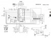
The problem is I used up all my I/O pins for this project
but i would like to add IR control so need one extra pin.

I have now used 1 for PIEZO / 2 for I2C sensors / 2 for 2 buttons / 2 for xtal /
1 for 2.5v reference for battery monitoring and the rest for the HDSP211x Display.
I also have ICSP on 2 wires of HDSPbus seperated by 2 resistors.

 
Last edited by a moderator:
Post your schematic. Some PICs have a built in battery (VDD) voltage monitor, the 16F886 doesn't appear to but the pin compatible 18F2525 does. You could then skip the 2.5V vref.

Also you might be able to squeak out an I/O by putting the 2 pushbuttons on a single input pin and driving them with the display data lines.

Do you need the crystal? Two pins available if not.
 
Last edited:
Do you mean I can use almost the same mikroc code on an 18F2525
and plug it in place of the 886?
 
The 18F2525 is more advanced than the 16F series, you would have to make changes to your code and your compiler must be for the 18F
Post your schematic.
 
Last edited:
I've added schematic.

I use mikroc for 16F 18F pics so transition should be straightforward?
 

Attachments

  • hdsp-circuit.jpg
    hdsp-circuit.jpg
    126 KB · Views: 1,861
MCLR can be changed into an input pin.

I see you have a battery backup, if it were my design I'd probably use a 32,768Hz watch crystal on TMR1 and the internal oscillator. This would allow for easier timekeeping and simple low power operation with timekeeping (you can sleep the PIC and wake it up every second or two to keep time)
 
Last edited:
Then mux the switches on the RB3,4 lines and put a pullup on the input pin. Use resistors or diodes to keep them from shorting when you press them both at the same time.
OR just use a bigger PIC like the 16F887
 
Last edited:
Simplest way to get a pin is to use the MCLR line as a dig. input and move one of the switches to it.
Have the switch take the pin logic hi on contact and have a 10K pulldown on the pin. This does not affect the ICSP unless u press the switch DURING ICSP.
So no jumper needed etc. If your current switch logic is 'low when on" just invert when sampling and all is good.
I have a 16F886 running like that now.
 
Great idea, Can i also have a diode in series with the 10k to isolate my onboard power from
the higher programming voltage ? I would expect this to be not a problem.

I always thought the MCLR had to be setup as external MCLR to be used as the ICSP.
I guess i thought that wrongly, after reading your reply.
 
U might need another blocking diode for the Vdd if u want to ICSP with a running app.
 
You still need VDD & VSS when programming. I don't see how blocking diodes would help.

I mean a blocking diode (+ve bias) in line with the pickit2 VDD supply. Thus Isolating the Pickit VDD from the system Vdd to prevent a current loop into the Pickit2. That would permit either the Pickit2 to supply Vdd or the system Vdd to do the job. Thus the system can be powered or unpowered and the programmer will work.
 
Last edited:
Status
Not open for further replies.

Latest threads

Back
Top