From your description its now sounding like the hardware is faulty if its not working as per the instruction sheet.
Why does it sound faulty? It is working exactly as it supposed to.
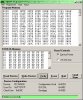
Currently, the function is as follows: each set of DIP switches can be set for seconds, minutes, or hours (red=on time, blue=off time ); Then they are set for the actual times, but since there are only 4 switches counting in binary, the highest times = 15. ie 1s - 15s 1m - 15m 1h - 15h']Currently, the function is as follows: each set of DIP switches can be set for seconds, minutes, or hours (red=on time, blue=off time ); Then they are set for the actual times, but since there are only 4 switches counting in binary, the highest times = 15. ie 1s - 15s 1m - 15m 1h - 15h
I can only go on the information you give , but I really think you have misunderstood how the switches set up the times.
To me it is clear from all those links and documents that the kit can do what ever times you need.
I suspect that lines like this have caused to you , mistakenly think it can only do 1 to 15.
Each DIP switch can be set to a binary value of 1 through 15 and can be configured to be in Seconds, Minutes, or Hours.
Thats not the case, it means you have 15 possible combinations of the 4 switches, BUT each position of the switch refers to at time as per those charts on the right hand side.
As an example
To set the RED on time for 40 mins.
First you must set the switches to select the time range for the 40 mins you want from the 8 - 120min range, so set switches 1-3 down and 4 up.
Do the same with the Blue switch for your off time range.
Then power up with the black switch pressed and you should see the led flash to say its accepted the Time Range.
Power off and then set the Red switches for the time you want.
Look at that 8-120 min chart and against the 40 mins you see the four settings for the Red switch so set 1 and 3 down and 2 and 4 up.
Do the same for your Blue Switch actual time.
Then power on and it should run for 40 mins .
Please do actually try it, I'm not there , but feel sure thats the correct way to get it working properly
Edit, the timing details in that document, where it says 8 -120 mins there is a little picture of the dip switch positions that for telling it to select the 8 -120m range.
The chart on the right is for setting the switches again for which one of the 16 times times you want from that range , so the 40 mins shows the required position of the switches