Continue to Site

Welcome to our site!

Electro Tech is an online community (with over 170,000 members) who enjoy talking about and building electronic circuits, projects and gadgets. To participate you need to register. Registration is free. Click here to register now.

  • Welcome to our site! Electro Tech is an online community (with over 170,000 members) who enjoy talking about and building electronic circuits, projects and gadgets. To participate you need to register. Registration is free. Click here to register now.

Pic to Pic rf communication circuit

Status
Not open for further replies.

pari88

New Member
Hi all,
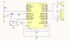
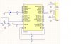
I am new to this forum. Please help me. I am designing PIC-PIC connection using rf link. I am using PIC18F4550. Could u all please comment on the circuit I have attached. I don't know whether the circuit is correct or need some addition. Thank you


Pin 25-->Tx
Pin 26-->Rx
Pin 13&14-->20MHz
Pin 11, 32-->Vcc
Pin 12, 31-->GND
 

Attachments

  • my rf circuit.jpg
    my rf circuit.jpg
    163.1 KB · Views: 831
Unless you are planning on using an RF module for communication that has some intelligence built into it, you will need a way to syncronise and recover your clock at both ends of the link. This is usually achieved by using a signal encoding method of some type, most commonly Manchester.
Without being able to sync and recover your clock, there will be no reliable way to send/ receive data.

I see from your schematic that you have two Micro's, LED's and a switch, but where are your transmitter/ receiver modules etc?

You will not be able to use the standard built in UART for your RF link, you will need to write the code for both transmit and receive and bit bang a couple of port pins. I have a vague memory that Nigel Goodwin has an example and tutorial of how to do this on his site, but I could be wrong. His tutorials are worth a look through in any case

rgds
 
Hi
I am working on a similar project..check for Manchester encoding. Look at microchip ap notes...TB045 is a good one.
Let us know how you get on.
Ray
 
I am sorry for the inconvenience before. Hereby, I attach the circuit for my transmitter and receiver. Could u all please help me take a look at it and give any comments. Thank you.
 

Attachments

  • Transmitter.jpg
    Transmitter.jpg
    116 KB · Views: 616
  • receiver.jpg
    receiver.jpg
    99.4 KB · Views: 496
Using the USART either software or hardware is possible but I found it to be problematic. What sort of data do you want to send? There may be better ways to do what you want....best to give more details.....purpose of application, compiler you are using etc.
Your circuit is not the biggest issue....it will be the code.
 
I want to read data from a sensor, log it to the first pic and transmit it to the second pic. I am using ccs pic c compiler. Hope u can help me design it. Thank you.
 
This sounds like remote temp monitor or other data collection. You need to tell us what type of data...how much..how often...how fast....etc.
Try to Google remote data or remote temp sensing.
 
I want to make a real time application. I am collecting temperature data. I want to display both time and data on Visual Basic (GUI).
 
I am sorry for the inconvenience before. Hereby, I attach the circuit for my transmitter and receiver. Could u all please help me take a look at it and give any comments. Thank you.

Sir, Can you please give the source code for this , i am doing the project on this so kindly post it immediatly
 
Status
Not open for further replies.

Latest threads

New Articles From Microcontroller Tips

Back
Top