Continue to Site

Welcome to our site!

Electro Tech is an online community (with over 170,000 members) who enjoy talking about and building electronic circuits, projects and gadgets. To participate you need to register. Registration is free. Click here to register now.

  • Welcome to our site! Electro Tech is an online community (with over 170,000 members) who enjoy talking about and building electronic circuits, projects and gadgets. To participate you need to register. Registration is free. Click here to register now.

pic port expander

MrDEB

Well-Known Member
While waiting for boards and parts I decided to venture to another project.
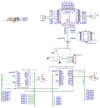
Using an 18f43k22 pic I want to drive 4 leds per port. Have used in another project 2 LEDs same color in parallel with one 330 ohm resistor and it works just fine but driving 4 LEDs may be pushing the limits of the pic.
Thus thinking about using a port expander.
ANY suggestions?
I recall Jon used a port expander in one of his projects.
 
Got to thinking that why not just multiplex as one does with a 8 x 8 matrix.
The 18f43k22 has 4 - 8 bit ports (A,B,C,D) plus the port E.0, E.1. E.2.
So basically 128 LEDs plus the E port.
This could work but ??
 
I'm assuming you've looked in to Charlieplexing?

Cheat sheet:- N= number of microprocessor outputs available.

charilieplexing.png
 
With four 8 bit ports you can do a 16x16 matrix giving you 256 LEDs. Assuming some pins will be otherwise used an 8x16 matrix could be used giving 128 LEDs. You may need additional drivers on the (psuedo) 16 bit port to handle more current (ULN should surfice).

Mike.
 
After reviewing and reliving some of the nightmares in this Christmas Star thread, which includes ALL of the advice offered again in the MOSFETs thread, I am absolutely certain I will have no further comments in this thread.
 
After drawing out a schematic using LOTs of resistors as per the Christmas Star project I looked at the Max7219 and being wary about the code to use I found on the swordfish forum a module for the max7219 so onword.
After drawing the schematic for using 2 Max7219 I am going to revamp my Christmas Star project using the Max7219
 

Attachments

  • Schematic_matrix-seahawk_2024-05-14.jpg
    Schematic_matrix-seahawk_2024-05-14.jpg
    96.1 KB · Views: 48
I ordered some Max7219 kits to try out the SF code.
According to the post#12 I run ouf of pins. going to wait for the kits before going further
 
I ordered some Max7219 kits to try out the SF code.
According to the post#12 I run ouf of pins. going to wait for the kits before going further

Why? - you only need three pins - for the SPI interface.

Why on earth have you connected the outputs of the MAX7219's to the PIC I/O pins?.
 
I misinterpreted page 13.
Looking at page 12, I wonder if I should include a Max394?

Are you driving 2.3 inch 7 segment displays?.

I would suggest you get the MAX7219's from AliExpress (or similar), as cheap kits with an 8x8 LED module, with both the LED module and the MAX7219 in sockets. You then pull the MAX7219's out of their sockets, and throw the rest away - it's a fraction of the price of buying just a MAX7219 locally.
 
I am driving multiple LEDs, basically 128 individual LEDs (blue and white).
I made several similar ones in my Christmas Star project, but I had pairs of LEDs in parallel with 1- 330 ohm resistors.
They work great but could use some improvement.
While waiting for boards for my sign project, I decided to start working on Christmas 2024. Thus, I am calling this project the SEAHAWK ornament for Christmas. After I get this project through the ringer, I plan to redo the Christmas Stars PCB.
 
Here is the schematic of the Christmas Star project but going to improve the design using a MAX7219
 

Attachments

  • Schematic_copy1_2020-08-29_12-52-14.pdf
    165.9 KB · Views: 37
Before I get too far and get lost, the Max7219 data sheet shows CLK INPUT ON PIN 13. What pin do I connect to the 18F43K22
Then
The LOAD (CS) pin 12 connects to pin? on the 18f43k22
then
DIN (data in)
 
HERE IS THE CODE FOR TESTING THE mAX7219. Hopefully I can test this out when I get the LED boards.
From what I decipfer, the CLK is portB-1 and the CS is portC.1 but where to connect the DATA connection?
I downloaded the code for 2 or more but will start with one Max7219
Code:
{
*************************************************************************
*  Name    : MAX7219.BAS                                                *
*  Author  : Ahmed Lazreg  (ahmed.lazreg@pocketmt.com)                  *
*            http://www.pocketmt.com                                    *
*            http://www.microcodeproject.com                            *
*  Notice  : Copyright (c) 20015 Pocket MicroTechnics                   *
*          : All Rights Reserved                                        *
*  Date    : 01/01/2015                                                 *
*  Version : 1.0                                                        *
*  Desc.   : Test program for MAX7219 module                            *
*                                                                       *
*************************************************************************
}

Program Max7219_test

Device = 18F452
Clock = 20

Include "utils.bas"
Include "convert.bas"

//#option MAX7219_SPI_SOFTWARE = true
Include "Max7219.bas"

Dim RED_LED     As PORTB.1

Dim i As Word

Sub Init_MCU()
    PORTA = %00000000
    TRISA = %11111100
    PORTB = %00000000
    TRISB = $00
    SetAllDigital()
End Sub

Init_MCU()
High(RED_LED)

// main program loop
SetDisplayTestMode(true)
DelayMS(300)
SetDisplayTestMode(false)
WriteDigit(6, SYMB_E)
WriteDigit(7, SYMB_P)
DelayMS(1000)

BlankDisplay()
WriteValue("HELP-. ")

DelayMS(1000)

BlankDisplay()
WriteDigit(7, SYMB_H)

i = 0
While (true)
        Toggle(RED_LED)
        DelayMS(800)
        WriteValue(DecToStr(i))   ' use FloatToStr(..) for floating point values
        i = i +1
End While

End Program
 

Latest threads

New Articles From Microcontroller Tips

Back
Top