Continue to Site

Welcome to our site!

Electro Tech is an online community (with over 170,000 members) who enjoy talking about and building electronic circuits, projects and gadgets. To participate you need to register. Registration is free. Click here to register now.

  • Welcome to our site! Electro Tech is an online community (with over 170,000 members) who enjoy talking about and building electronic circuits, projects and gadgets. To participate you need to register. Registration is free. Click here to register now.

Pic in a light switch

Status
Not open for further replies.

ztech

New Member
I want to put a PIC in a light switch. All I have available the Netural line and Live via the light blub. I thought I would put a i.e 47R 3W resistor in the line to draw some volts/current, rectify to DC to drive my PIC. Does anyone see any potential problem with this method? Has anyone done anything similar? TIA
z
 
i think that is very wrong no one use a resistor to drive a pic all people use regulators to adjust the voltage level to 5 volt
if you want to switch the lamp with thw pic u can use a port as an output and use it with conjunction with a relay circuit that can carry 220 volt
 
Thank you for your reply. I didn't mean directly but the basic theory of the R to divide down >rectify > drive the PIC. My problem is what do I do when the switch is turned off. Maybe I put a large R across the switch to allow a small amount of volts to pass when switch is open. I feel I am missing somethig here. Maybe I try this out and report back.
z
 
so when you have the swich closed the light is in series with the resistor and you get a voltage drop on the resitor wich you use for the pic right?
well if you dont mind putting a diode in series with the lamp, then i think i can help.
here is an idea of what i am thinking. the value of the components need to be changed acording to how much voltage you want and how much power.the circuit will work in the same way with the switch onpen and closed.
by the way, sorry for the low quality drawing.
 

Attachments

  • scan0021.jpg
    scan0021.jpg
    58.1 KB · Views: 1,236
Thanks for replying and your drawing is just fine. My solution is much the same except I used a 47R 3W resistor instead of the diode to keep the brighness up. I have not found the optimum values for given bulb wattage but will post my finding when I finish.
z
 
I thought I would complete my original post with my findings of this circuit. It's not elegant but works. :p 
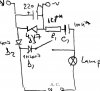
Thank you for all the replies. Maybe someone can improve on it?? (sorry for the sketch) :( z
**broken link removed**
 
from my calculations, for a 100W lamp, you have a disipation of about 8W on the reistor.....
i think that a 3W resistor can hold that kind of current, if it is ceramic.
but i think that it will overherat, and because it is in an closed space( if you have it in the switch) you might have a fire danger.
what do you have to say about this?
 
:idea:

In other deisgns for powering pic's etc from the mains a high voltage capacitor is normally used to drop the voltage (to then be regulated).

This has the advantage of not generating any heat, the cap has to be chossen for your required voltage and frequency (i.e. 240/50hz, 100/60hz etc).

I think that microchip have an app note on powering pics from the mains.... check out www.microchip.com

:wink:
 
Status
Not open for further replies.

Latest threads

New Articles From Microcontroller Tips

Back
Top