Hi everyone.
I am working on a project which has an op-amp (measuring very high temperatures).
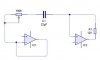
The op-amp has a variable sensitivity function, which uses a 100K potentiometer, wired up as shown in the attached image.
I want to make this resistance adjustable by a PIC, but I am not sure how to go about it. I cannot use a digi pot or a DAC, as the potentiometer is not across a fixed voltage, and all the digi pots I have seen require one end to be grounded. Aditionally, the circuit operates of 12V, and I have not seen any digi pots that can run off that.
Does anyone have any idea on how I can make the sensitivity varied? Relays and resistors (in parallel) would work, but be very messy. Replacing the relays with two 4066s would be a little neater, but still not great.
Many thanks
Richard
I am working on a project which has an op-amp (measuring very high temperatures).
The op-amp has a variable sensitivity function, which uses a 100K potentiometer, wired up as shown in the attached image.
I want to make this resistance adjustable by a PIC, but I am not sure how to go about it. I cannot use a digi pot or a DAC, as the potentiometer is not across a fixed voltage, and all the digi pots I have seen require one end to be grounded. Aditionally, the circuit operates of 12V, and I have not seen any digi pots that can run off that.
Does anyone have any idea on how I can make the sensitivity varied? Relays and resistors (in parallel) would work, but be very messy. Replacing the relays with two 4066s would be a little neater, but still not great.
Many thanks
Richard