Continue to Site

Welcome to our site!

Electro Tech is an online community (with over 170,000 members) who enjoy talking about and building electronic circuits, projects and gadgets. To participate you need to register. Registration is free. Click here to register now.

  • Welcome to our site! Electro Tech is an online community (with over 170,000 members) who enjoy talking about and building electronic circuits, projects and gadgets. To participate you need to register. Registration is free. Click here to register now.

Pic controlled channel change and led & 7 segment display 0-99

Status
Not open for further replies.

don282

New Member
Hi all, I am a new member but I am not a programmer, have been in electronics all my working life mainly in RF.
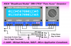
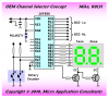
I am refurbishing/updating some older 2way radios for ham use and need a method of channel changing. Basically I need a replacement for 2 BCD thumbwheel switches. I have rotary switches that have 2 sets of contacts, 1 makes and breaks in one direction and the other makes and breaks in the other direction, these will need to be debounced. I want to use these as the input device. On the other end I need 2 BCD outputs to select the eprom outputs selectable to be active high or active low. My next requirement if possible would be to have each of the BCD outputs drive a 7 segment display and be independant of the active state of the BCD outputs.
I would like to use a PIC if possible (16F84 or similar) I have a pic programmer and have programmed a number of them from someone elses HEX files.
Can anyone point me to someone who may have done this before, I imagine it would have been done many times but it is beyond my programming capabilities. I can visualise what needs to happen but what happens inside the chip no way, I'm lost.
TIA.
Don....
 
Last edited:
Hi Don,
What you're asking may have been done before, but I couldn't understand all of your description.

So you want to use 2 rotary switches as direct replacements for the 2 BCD switches?

On the other end I need 2 BCD outputs to select the eprom outputs selectable to be active high or active low.
You lost me. Are these BCD outputs any different to the BCD thumbwheel switch outputs (apart from the selectable active level)? So is this correct: "On the other end I need 2 BCD outputs which may be configured to be active high or active low."

My next requirement if possible would be to have each of the BCD outputs drive a 7 segment display and be independant of the active state of the BCD outputs.
Please explain.

I can visualise what needs to happen
I can't ;). Feel free to either clear up the above or to attach a drawing of what you want.
 
I'm also having a problem understanding what your requirements are.

From your description it sounds like,
You have 2 switches with 2 outputs each that connect to 4 input pins of a pic.
The inputs will increment/decrement 2 BCD outputs, so 8 output pins.

What will the 7seg display if not the BCD values?
Do you also have a link to the rotary switches?

Mike.
 
Hi, sorry for the confusion. The aim is to replace a 2 pole BCD switch that is faulty and unobtainable because of its small size. I have 1 switch that has 2 poles, 1 pole is activated by turning the switch anti clockwise the other pole is activated by turning it clockwise producing a brief closure for each click depending on the direction of rotation. This switch is used for channel changing in a commercial mobile radio and it supplies the pulses for up and down channel changeing. From these pulses I need to provide 2 BCD outputs that can be selected to be active high or active low (selected by a link) that are connected to the address lines of an EPROM that contains the data for the phase locked loop. And to keep things simple I need to have the Pic drive two 7 segment displays. the 7 segment displays must not be affected by the fact that BCD to the eprom could be active high or low and I would prefer not to have to add any extra chips to cope with the different active states. I have 3 of these radios and 2 are 1 type and the other is the reverse hence the need to change the active state.
I hope this explains it.
TIA.
Don...
 
Hi Don,

How many channels, 00 through 99? What is the range of BCD (address) codes? Does it start at 0000.0000 (chan 00) through 0110.0011 (chan 99) or some other range?

Mike
 
0110.0011 (chan 99)
BCD 99 would be 1001.1001.

Don, do you want 2 rotary encoders or just the one? You only need 1, but 2 allows you the make big channel jumps quickly.
 
Hi all, all I want is 0-99 on the led display and BCD 0000 - 1001 from each BCD output to drive the eprom address lines selectable active high or active low. this makes it useable in other projects as well and just 1 rotary pulse generator.

Don...
 
Thanks for the clarification Don.

Many of us have written code for bits and pieces of your application so it shouldn't be too difficult getting help from the forum.

I'm guessing that you will need 8 pins to drive a 2-digit 7-segment LED display, 8 pins for the dual 4-bit BCD outputs (eeprom address lines), and another 2 pins for the rotary up/down pulse switch. That's 2 more I/O pins then what you have available on an 18-pin PIC. You may have to upgrade to a 28-pin PIC or add another relatively inexpensive IC (like a 74HC595).

I'm sure someone will mention using discrete LEDs instead of 7-segment displays because you could drive them with 5 pins as a Charlieplexed matrix but I personally think that discrete LEDs don't look as nice as the 7-segment displays.

C'mon guys. Any ideas on how to fit that all on an 18-pin PIC? Perhaps connecting the two switch inputs onto a couple segment driver lines and reading or polling them periodically? No, never mind, that won't work because one of those sixteen I/O pins is usually input only and we need sixteen outputs.

Regards, Mike
 
Last edited:
C'mon guys. Any ideas on how to fit that all on an 18-pin PIC?
Sorry, not without an extra IC or some horrible passives (RC)

Perhaps connecting the two switch inputs onto a couple segment driver lines and reading or polling them periodically?
That'll work; you just need enough pins or an expander (or decoder e.g. 7447)
 
Thanks to everyone, I would not mind going to a 28 pin device but I also have an other solution and that is for one of these units I could delete the need to handle the LED drivers and just use the BCD output to drive a couple of Texas TIL308 displays which have BCD input and have decoding and a 7 segment display in one package, only problem they are not made anymore and have small digit size but I have 2, the other option is to use 4511 BCD to 7 segment drivers, messy!. I think I like the larger 28 pin Pic idea. I can handle programming most PIC's and I think it is DSP? chips with a Silicon Chip programmer (around May 2008) it does up to 40 pin chips.
Another question, would the routine for doing the rotary switch input in the 28 pin Pic be transferable to say 16F84 , boy I have a lot to learn!!! . Are there any cookbook type sites that have routines for things like I am trying to do, sort of like modules for different purposes?.
Many thanks ,
Don .... VK3YV......
 
I would not mind going to a 28 pin device
That will save you having to use extra chips.


the BCD output to drive a couple of Texas TIL308
That won't work if you still require the active high/low sense of the BCD output.

Another question, would the routine for doing the rotary switch input in the 28 pin Pic be transferable to say 16F84
Not if the wiring changes (will require a rewrite). Otherwise it's possible.

Are there any cookbook type sites that have routines for things like I am trying to do, sort of like modules for different purposes?.
Yeah, there are people that put routines for certain purposes on the net. In all different languages and programming styles, I prefer just to write my own. A quick google should help you here.

If you're happy with using the TIL308 then it can be done in an 18pin pic16f628, no worries. As you only have 2, I can't see how you'll upgrade 3 radios. You can use a single 7447 type BCD decoder to drive both displays and use the 18pin pic (you'll also need 2 transistors and 4 resistors).

Just say which way you want to go.
 
I think the way to go will be with the 28 pin Pic. If I go the TIL308 way and lose one Im stuffed, and I dont know if anyone else has ever made a chip like the TIL series.
What ever you can come up with will be most appreciated , let me know what Pic you would suggest and I will arrange to get some and also get some data on it. I have collected quite a pile of Pic stuff from Microlab and all I have to do is sort it on the hard disk into some sort of order that I can find again! I need to find some practical applications that I can relate to and see what the source code is to do it as I have done no programming at all and the years and memory these days are going to make it hard, Oh well they say it happens.
Many thanks,
Don....
 
I'd suggest one with an internal RC oscillator and sufficient pins. If you're using 5v in the radio, then get a pic that can run from 5v.

you'll need at least 17 output pins (more won't hurt):
8 outputs - 2 x BCD
9 outputs - 2 x 7seg display + 2 column drivers.

all switches can be connected to the 7 seg row pins, or you can include an extra (input) pin for each switch. Either way is fine.
 
Hi dougy, I have been tryingto find a PIC that meets the requirements and also that I can program, man how things change in a couple of years. I first came up with a 16F1933 but that is not even stocked by Farnell yet, next I looked at what my programmer lists (That is 18 months old) and came up with 18F2320 and Farnell only have one in Australia. Have you any suggestions, the programmer says it will program most PIC's in the DIP package and all dsPIC30F series in the DIP package, it uses WinPic freeware for Windows and is connected to a serial port. (Silicon Chip May 2008)...

Don...
 
Don,

I'm just wondering if that Up/Down Rotary switch you have might actually be a Rotary Encoder? I haven't come across anything that puts out seperate Up/Down pulses as you turn it but I use relatively inexpensive mechanical Rotary Encoders with detents to provide that exact same function.

It's not a big deal to code an input routine for a Rotary Encoder or your OEM Up/Down switch but I just thought I'd mention it because if you have a hard to find OEM switch and it breaks then you might consider replacing it with a Rotary Encoder. The ones I use have 16 detents per revolution and a built-in push button switch on the shaft (drawing below).

Regards, Mike
 

Attachments

  • BB-CTCSS Tone.PNG
    BB-CTCSS Tone.PNG
    35.2 KB · Views: 1,166
Last edited:
Hi Mike, I have been looking for one of the switches today but the bag of them has eluded me, I am sure they are just direction selective momentary contacts. They were used for just the purpose I want to use them for. There was a variation used in the model previous but its operation was different in as much as they were not rotary you had to hold them in either direction against a spring and I believe it was not a popular means to change channels by hence the change. The controls were made by ALPS and they were interfaced to the micro that was in the radio and the radios had many more channels than the switch had positions, you just kept turning the knob. There are only 4 connections to the device 2 on each side and they meter out just as a closure and there is no continuity between either switch...
I will keep looking and see if I can track the ALPS number but they may be to old now. the switches I have are as good as brand new as we removed all control functions from the radios and replaced them with a dash top data terminal and GPS.
Thanks,
Don.....VK3YV....
 
Ok Don. Like I said, writing code for your OEM up/down switch or a Rotary Encoder is not a big deal.

So it seems we're looking at a design that might look something like this (below) using a 28-pin 16F' or 18F' device with any number of simple design variations for the display, switch, etc.. Does this look correct to you and other Forum members (yes, I know the "ones" driver transistor needs a pull-down resistor on its base)?

I can't help thinking that this entire circuit could be replaced by a pair of BCD thumb-wheel switches which would display the channel number and drive the eeprom address lines. You would just need to connect +5v or ground to the "common" lines on the thumb-wheel switches to change the output polarity.

oem-channel-selector-png.38892
**broken link removed**

On the software side I was thinking there may be a couple advantages using a single packed BCD "channel" variable in the software. (A) you can write the packed BCD "channel" variable (inverted or non-inverted) directly to the eprom output port, and (B) the displays are easier to refresh without the need for a binary-to-decimal routine. The down side is that incrementing or decrementing a packed BCD variable uses a few more instructions.

Code:
;
;  ISR "display driver" code (8-msec intervals = 62.5 Hz refresh rate)
;
refresh
        movf    PORTB,W         ; WREG = PORTB                    |B0
        andlw   0x80            ; clear the b6..b0 segment bits   |B0
        xorlw   0x80            ; toggle b7 digit select bit      |B0
        movwf   PORTB           ; blank display, select new digit |B0
        swapf   channel,W       ; W = 'tens' in right nybble      |B0
        btfss   PORTB,7         ; tens display? yes, skip, else   |B0
        movf    channel,W       ; W = 'ones' in right nybble      |B0
        call    segtbl          ; get digit segment data          |B0
        iorwf   PORTB,F         ; display new digit               |B0
Code:
;
;  segment data table (caveat, non-boundary tolerant)
;
segtbl
        andlw   0x0F            ; strip off upper nybble          |B0
        addwf   PCL,F           ;                                 |B0
        retlw   b'00111111'     ; "0"   -|-|F|E|D|C|B|A           |B0
        retlw   b'00000110'     ; "1"   -|-|-|-|-|C|B|-           |B0
        retlw   b'01011011'     ; "2"   -|G|-|E|D|-|B|A           |B0
        retlw   b'01001111'     ; "3"   -|G|-|-|D|C|B|A           |B0
        retlw   b'01100110'     ; "4"   -|G|F|-|-|C|B|-           |B0
        retlw   b'01101101'     ; "5"   -|G|F|-|D|C|-|A           |B0
        retlw   b'01111101'     ; "6"   -|G|F|E|D|C|-|A           |B0
        retlw   b'00000111'     ; "7"   -|-|-|-|-|C|B|A           |B0
        retlw   b'01111111'     ; "8"   -|G|F|E|D|C|B|A           |B0
        retlw   b'01101111'     ; "9"   -|G|F|-|D|C|B|A           |B0
Code:
;
;  increment "channel" if channel < upper_limit (99)
;
ChanInc
        movf    channel,W       ;                                 |B0
        addlw   7               ; increment + bcd adjust?         |B0
        skpdc                   ; yes, skip, else                 |B0
        addlw   -6              ; increment only                  |B0
        movwf   channel         ; update 'channel' var            |B0
        return                  ;                                 |B0
;
;  decrement "channel" if channel > 1
;
ChanDec
        movf    channel,W       ;                                 |B0
        addlw   -1              ; decrement only?                 |B0
        skpdc                   ; yes, skip, else                 |B0
        addlw   -6              ; decrement + bcd adjust          |B0
        movwf   channel         ; update 'number' var             |B0
        return                  ;                                 |B0
What programming language are you going to use? Assembler, BASIC, C? Which PIC are you going to use? Will your programmer work with that particular PIC?

More later. Regards, Mike
 

Attachments

  • OEM Channel Selector.PNG
    OEM Channel Selector.PNG
    28.3 KB · Views: 2,550
Last edited:
Hi Mike, the circuit you sent is exactly what I want even down to the pic box, its empty just as my knowledge of what is in there and how it works! Regarding the comment that it would be easier to put in 2 BCD thumbwheel switches, well that is what I am taking out as they are faulty mechanically and I cannot get any that are small enough to fit, and on checking with Farnell the prices are way out, I can buy 5 PIC16F886's for the price of just 1 BCD switch, no end plates or screws and into the bargain they are all to big. I don't have much room behind the panel, I have already trimmed the contact connections and the circuit board behind them and put some mylar in to stop them shorting, so out with the old and in with the new both physicaly and hopefully in my head (learning about PIC's) so be gentle I turn 67 in a couple of weeks and the only thing I have ever done as far as programming goes was way back in the late 60's when I played around with a 6800 and a 6809 but couldn't get my head around, it I am a practical hardware person in many fields, now by need I have to try and change. Some answers and questions. I presume whatever I do will have to be in Assembler, suggestion? please. My PIC Programmer does not list the 16F88X series but lists the 16F87X but the program that runs it WINPIC does list the 88x series and checking pinouts they look to be the same but the method of programming it has me confused but I think it will work. I am ready to order 5 16F886-I/SP's if it will work (28 pin dips). What does the -I and the -S mean I can't find any reference to it. What do I have to aquire to produce a hex file for the programmer? and what is packed BCD.
Enough for now just need to know if what I suggested will work so that I can order them and hopefully you can set me straight with my other questions.
Regards, Don....
 
Last edited:
I presume whatever I do will have to be in Assembler, suggestion?
You can use assembler, C, C++, BASIC etc. - you just need to get a compiler. There are a number of freebies and free trials. Microchip, hitech, boost-c/c++/basic (sourceboost: Index of /Products), crownhill and others supply limited compilers for free. They will be sufficient for your purpose.


16F886-I/SP's if it will work (28 pin dips). What does the -I and the -S mean I can't find any reference to it.
-I is industrial temperature range. /SP is the package type (SPDIP)

What do I have to aquire to produce a hex file for the programmer?
One of the afforementioned compilers or an assembler. Or ask nicely and a .hex might just turn up.

and what is packed BCD.
It's just plain old binary. BCD is where each nibble (4 bits) is used to represent a digit 0-9, so 8 bits of BCD can go from 0-99. 8 bits of what was called 'packed' (above) binary has a range of 0-255.

Good luck!
 
Status
Not open for further replies.

Latest threads

New Articles From Microcontroller Tips

Back
Top