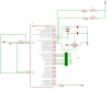
Finally managed to produce a circuit diagram for this, and would welcome help on the original question again. I have since simplified the circuit to remove various transistors and seven segment displays, and now it uses just an LCD display and a couple of switches, plus a few other supporting components.
The original problem still exists - if I remove the resistor R2, the circuit behaves as though the interrupt used for the hall effect is continually firing, resulting in a speed reading of about 196mph even though the hall effect switch is not being activated. Put R2 back in and the circuit is stable again.
I tried switching to a 12v car battery in case the 'wall wart' was producing noise, and using a 7805 with it. This results in about 4.85v supply voltage. This made no difference to the problem and additionally at this level, the PIC doesn't seem to behave correctly - it often fails to read values correctly from the EEPROM data, which is a bit weird but maybe this is all caused by whatever my circuit issue is anyway.
I obviously have the backlight on the LCD connected (through a 270ohm resistor), and the contrast is also connected through a resistor. These aren't on the schematic but they are in the circuit. LCD output is working properly.
I tried putting a 0.1uf capacitor across the power pins as suggested, but this had no effect either.
Thanks,
Richard.
 hm:?
hm:?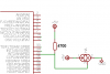
")

