Continue to Site

Welcome to our site!

Electro Tech is an online community (with over 170,000 members) who enjoy talking about and building electronic circuits, projects and gadgets. To participate you need to register. Registration is free. Click here to register now.

  • Welcome to our site! Electro Tech is an online community (with over 170,000 members) who enjoy talking about and building electronic circuits, projects and gadgets. To participate you need to register. Registration is free. Click here to register now.

PIC 16f877a alarm clock

Status
Not open for further replies.
Alarm clock with PIC (Thomas' Webpages)


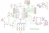
could someone help me with this.. I don't understand why the other capacitors and resistors in the schematic diagram have no value.. and only 10 pins of the lcd is used.. please help me..

hi,
I have added the values I would use.
Did the link have a Parts List file.???

The MAX232 is a dual TXD/RXD device, only one pair is used, thats why the other pins are not connected.
 

Attachments

  • schematic.png
    schematic.png
    100.6 KB · Views: 1,815
Last edited:
Thanks for the values you indicate in the schematic, i will try to use that resistors & capacitors..
I didn't find any parts list in this link but only in the schematic..

thanks again for info in max232.. i have another question, he only use 10 pins of the 4x20 LCD but the LCD has 16 pins.. I want to know what pins did he use, could you help me?..
 
Just guessing: he is using 4 bits only in the data bus? For the other two not used, I cannot guess anything.
 
Just guessing: he is using 4 bits only in the data bus? For the other two not used, I cannot guess anything.

thanks atferrari!.. I think he only use 4 bits and the other 6 pins would be from the ground which is pin1 up to clock(enable) which is pin6..
 
thanks atferrari!.. I think he only use 4 bits and the other 6 pins would be from the ground which is pin1 up to clock(enable) which is pin6..

hi,
As you have seen, LCD 4 data lines, Enb and RS lines. [with the R/W line to 0V..??]
The backlight line is driven from the transistor and 50R.

I would check how the Vcontrast line is connected.???
 
hi,
As you have seen, LCD 4 data lines, Enb and RS lines. [with the R/W line to 0V..??]
The backlight line is driven from the transistor and 50R.

I would check how the Vcontrast line is connected.???

Have you checked the connections from pic to lcd?.. i think my connections was right, i looked at the images of the finished project..
 
hi guys,
am doing a project on clock trigger device. in that am planing to give a transformer less(cost effective) power supply is their any major problem can occur, didnt work with such kind of power supply. will thankful for your opinion.

regards
thomasplam
 
hi guys,
am doing a project on clock trigger device. in that am planing to give a transformer less(cost effective) power supply is their any major problem can occur, didnt work with such kind of power supply. will thankful for your opinion.

regards
thomasplam

1. Don't use a transformerless supply, it's very dangerous.
2. Start your own thread, don't hijack this one.
 
I already try the project but the LCD's output was blocks and blinking.. I think it is running, but there are no data that was input to the LCD.. Can someone help with this problem..
 
Status
Not open for further replies.

New Articles From Microcontroller Tips

Back
Top