wuchy143
Member
Hi,
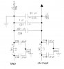
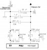
I have been looking at discrete PI filters for my boards and was wondering what people typical do when filtering power rails. Specifically the GND rail. If you look at my attached file you see both +5v and GND as the inputs. I'd like to also filter GND but looking at how I have it set-up C18 is doing absolutely nothing. I've seen people attached the C18 directly to chassis. Is that the best way to deal with this? If not what's a better way? Better filters out there?
Please note: PWR rails only will be delivering a max of 500mA at 5v. There is no high speed on my PCB. There is a PWM controller for a bank of 100 leds intensity. There is a PIC18f45k50 on there doing some basic capacitive sensing. Really nothing too exotic.
Thanks!