Continue to Site

Welcome to our site!

Electro Tech is an online community (with over 170,000 members) who enjoy talking about and building electronic circuits, projects and gadgets. To participate you need to register. Registration is free. Click here to register now.

  • Welcome to our site! Electro Tech is an online community (with over 170,000 members) who enjoy talking about and building electronic circuits, projects and gadgets. To participate you need to register. Registration is free. Click here to register now.

phase shift in homemade current probe

Status
Not open for further replies.

bre

New Member
Hi guys,

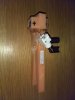
recently I made a current probe with the idea to measure the current coming out of my homebuilt power amplifier on my oscilloscope. I have a dummy load
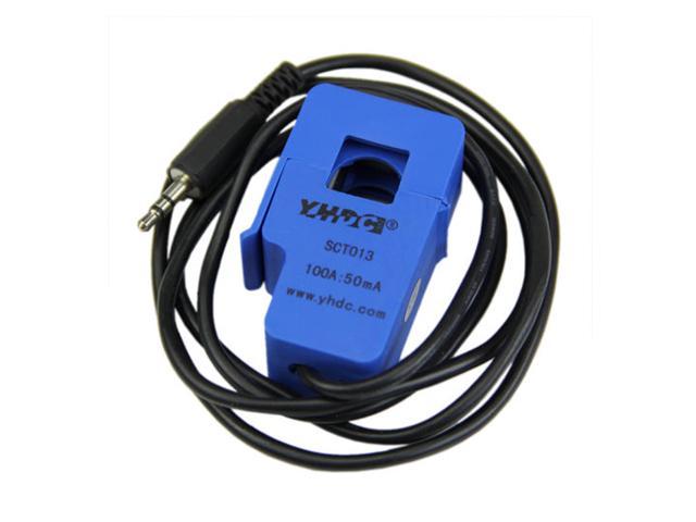
and can measure the voltage to deduce the current, but for learning purposes I also wanted to build a current probe to sense it directly. The probe is essentially a
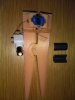
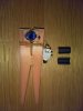
split-core current transformer with a single turn primary and a 50 turn secondary, with a 470 Ohm resistor across the secondary. The transformer is clamped around
the cable and a BNC plug goes across the resistor to the scope. The frequency of interest is in the 100kHz range. When I measure the voltage across a purely resistive
50 ohm load and compare to the current measured with the current probe, for some reason i see a large phase-shift (something like 40deg). Does anybody with
more knowledge know why this is and how it can be corrected? I tried putting a capacitor across the secondary to cancel the inductive reactance and thereby set a
"0 degree" point to which I could compare loads that have an inductive or capacitive component, but that only works for a single frequency. I'd appreciate any input. Thanks
 
Does this help?
https://electronics.stackexchange.c...degree-phase-shift-with-a-current-transformer

The thread seems to indicate that your 470R burden resistor is far too high and your turns (relative to the R) is too low, so an overly large resistance so the current transformer is not as transparent to the circuit as it should be.

I'm just parroting what the thread I linked is saying so you should read the thread for an explanation on why that is. I can only elaborate on my understanding of the post I linked to. The explanation's implications seems inline with why your addition of a capacitor works at only one frequency: After the RC is reflected from the secondary to the primary to be in parallel with the primary inductance, it would appear as a parallel RLC resonant circuit with an impedance valley at the resonant frequency. At this frequency, the CT would be transparent to your circuit by presenting the lowest possible impedance and load down your circuit the least removing any phase shift. I bet this is your one frequency where the addition of the C works. But basically, your loads on the secondary are too high and your turns ratio are too low so after the loads get reflected from the secondary to primary to be in parallel with the primary inductance, it loads down the circuit too much because the reflected loads are too high so all the current wants to flow through the primary inductance so it's like if you just plunked down an inductor into your circuit which causes a phase shift.
 
Last edited:
  • Like
Reactions: bre
what are you using as a reference for phase angle? the amp input or the output? most amplifiers are going to have a bit of phase shift between the input and output beginning somewhere between 1 and 3khz. by the time you get to the frequency where the amp gain drops to unity, it should remain short of 180 degrees phase shift (if it doesn't and you get to 180 degrees while there's still some gain, you have a big oscillator).

if you are using the output voltage for your oscope trigger, the phase shift is from the RL circuit that you are using to sense the current. one way to correct this is to insert a 0.1 ohm/5 watt resistor between the ground return from your load resistor and the amp ground. use the oscope to measure the voltage developed across the 0.1 ohm resistor and you have your current measurement. just multiply the voltage across the resistor by 10, and that gives you the current in amperes.. it's a lot better than trying to calibrate an RL circuit which is going to have phase shifts and amplitude changes that are frequency dependent.
 
  • Like
Reactions: bre
50 turn secondary
Do you have a way to measure the open circuit inductance of the 50 turn secondary? This will give me much information.
Please post a picture.

I have made many current probes and have many HP probes.
 
  • Like
Reactions: bre
When I have worked with current probes, I notice that the burden resistor plays a very important role in phase shift....it should be very low.

Even if you had a zero ohm burden, the transformers current would exhibit some phase shift, because of the secondary winding has some resistance of its own.
 
phase shift, because of the secondary winding has some resistance of its own.
No. The wire resistance and the burden resistance causes a voltage divider with no phase shift. It takes a L or C to get phase shift.

I have some 100:1 CTs that ate something like this:
1544806887893.png

The low end frequency response and phase shift is a function of R2 and the secondary inductance. (R2_R1)
The high end frequency responce and phase shift is a function of the secondary inductance and C1 (inter-winding capacitance). (or the self resonance frequency of the CT)
1544806988914.png

Some of my projects have a 3 way switch. (1,000 ohm, 100 ohm, 10 ohm)
The 1000 ohm has bad low end response but can measure low current.
The 100 ohms is per the transformer maker's specification.
The 10 ohms is very good at low frequency and high current. (Because the wire resistance causes some errors I needed to use 11 or 12 ohms)
 
  • Like
Reactions: bre
You are correct
Perhaps I should have used a more complete sentence: the wire resistance in conjunction with the inductance.

The effect is going to be small, I agree, but nevertheless is there.
 
Hi guys, thanks for all the input.

unclejed613 the reference for the phase angle is the voltage across the dummy load connected to the output of my amplifier. This already gives me the current because i know the load resistance, but the whole idea is to make a current probe and measure it directly :)

ronsimpson The open-circuit inductance of the secondary is 1.33 mH, and the series resistance of the secondary is 0.74 Ohm. A few pics of the probe
are shown below - the split core I used was a cheap clamp-on ferrite for spike suppression. In your schematic I see your secondary
inductance is much higher relative to your primary, compared to my case, and that you also have lower R2 values compared to me, except
in the 1000 Ohm case. I'm looking to measure current of several hundred mA to maybe 2-3 A. So, does this mean that I should increase
the secondary windings, lower R2, and settle for a lower voltage range measured across the resistor?
 

Attachments

  • cp_1 (1).jpg
    cp_1 (1).jpg
    371.7 KB · Views: 182
  • cp_2 (1).jpg
    cp_2 (1).jpg
    483.6 KB · Views: 181
  • cp_3 (1).jpg
    cp_3 (1).jpg
    627.5 KB · Views: 188
First, great job on the mechanics. I wish I could do that.
Your inductance is low and the resistance is high so the frequency is -3db at 85khz and the phase is off too much. My guess is that the phase is 40 off at 100khz. f = R/(2 pi L) You can check this by changing to 100 ohms and see if the phase corrects. ( the output voltage will be 1/10)
1544832333086.png
 
  • Like
Reactions: bre
I use these from coilcraft.com and others.
**broken link removed**
Notice these use very low resistors and the inductance is higher.
1544833126336.png
 
  • Like
Reactions: bre
ronsimpson thanks Ron, I used my Tevo Tarantula 3D printer for the clamp fabrication. I have some ideas for a nicer design in the future :)

I think I understand now what the problem is with the current probe. I will see if there is enough room to play with the turn number and load
resistance, since I still have a few of the split-cores lying around. If not then I'll look into the coilcraft current transformers, they look quite neat.

Thanks for the help!
 
I think this one (split core) is designed for 50/60hz and does not work well at 100khz.
I would pay the $9.00 just to get the core and turns. Gut the part and put it in your printed clamp.
ABV7_131217612112311463oT6PVhLqbM.jpg

If you are shopping for CTs, there are two groups. There are the 50 to 60hz that work through the audio range. There are TCs that are built for PWM at 30k through 1mhz.
 
  • Like
Reactions: bre
Status
Not open for further replies.

Latest threads

New Articles From Microcontroller Tips

Back
Top