Beau Schwabe
Active Member
Just a typical project: (a little cross humor)
1) From a concept scratched out on a napkin or whiteboard you have an idea for a circuit.
2) You test the heck out of it and along the way you want to give it some smarts.
3) So now you have to write some firmware and test the firmware
4) Now there is a bug in your code and you have to fix that
5) Back to testing the functionality and if your happy with that ... time for the PCB, but first make sure your schematic is correct
6) Run a BOM ... once you see the sticker shock you might need to revisit the design or select alternate components
7) Wow, you just had an epiphany with your design and without sacrificing functionality you figured out how to cut out half of the components.
8) Now the BOM is way down the PCB artwork design can finally go underway
9) You submit your PCB gerber files to your favorite boardhouse and order all of the required components,
10) While waiting for the PCB's to arrive you optimize your firmware code
11) Components arrive ... usually before the PCB's
12) PCB's are finally here and ready to be populated and tested.
13) Load all of the necessary firmware on PCB through an ICSP
14) The "first light" is always a bit of nervous anticipation and can be a little delicate ... one wrong component orientation, solder bridge, etc, and POOF the magic smoke comes out.
15) And then ..... Success!! The project below was much more involved than the steps above, but it had it's moments.
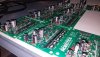
I always find this kind of visual so mesmerizing and personally satisfying to me ... From design, to firmware programming, to layout, to PCB population, to testing here is a little something I'm working on. For low volume runs I personally populated the PCB's by hand.
This basically a high current high voltage 48V DC motor controller, but that's where it stops being like most other motor controllers ... Our particular project requires hundreds of motors ... Aside from power management, this is an addressable (up to 65536 unique addresses) motor controller that can communicate over an RS485 network by sending structured data packets to send and receive data to and from the controller.
1) From a concept scratched out on a napkin or whiteboard you have an idea for a circuit.
2) You test the heck out of it and along the way you want to give it some smarts.
3) So now you have to write some firmware and test the firmware
4) Now there is a bug in your code and you have to fix that
5) Back to testing the functionality and if your happy with that ... time for the PCB, but first make sure your schematic is correct
6) Run a BOM ... once you see the sticker shock you might need to revisit the design or select alternate components
7) Wow, you just had an epiphany with your design and without sacrificing functionality you figured out how to cut out half of the components.
8) Now the BOM is way down the PCB artwork design can finally go underway
9) You submit your PCB gerber files to your favorite boardhouse and order all of the required components,
10) While waiting for the PCB's to arrive you optimize your firmware code
11) Components arrive ... usually before the PCB's
12) PCB's are finally here and ready to be populated and tested.
13) Load all of the necessary firmware on PCB through an ICSP
14) The "first light" is always a bit of nervous anticipation and can be a little delicate ... one wrong component orientation, solder bridge, etc, and POOF the magic smoke comes out.
15) And then ..... Success!! The project below was much more involved than the steps above, but it had it's moments.
I always find this kind of visual so mesmerizing and personally satisfying to me ... From design, to firmware programming, to layout, to PCB population, to testing here is a little something I'm working on. For low volume runs I personally populated the PCB's by hand.
This basically a high current high voltage 48V DC motor controller, but that's where it stops being like most other motor controllers ... Our particular project requires hundreds of motors ... Aside from power management, this is an addressable (up to 65536 unique addresses) motor controller that can communicate over an RS485 network by sending structured data packets to send and receive data to and from the controller.